Robotic Endoscope Controller
Device that would allow the surgeon to manipulate an endoscope using a handheld joystick.
Motivation
To perform diagnostic or therapeutic minimally invasive procedures inside the digestive tract, the surgeon uses an endoscope - a flexible tube with a camera, air and water source, suction and an instrument port all packaged to operate from the distal tip.
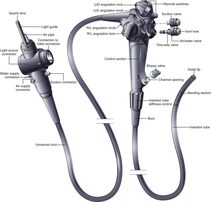
To steer the tip and control these features, the surgeon manipulates the handheld “control head,” which has angulation knobs and locks that are rotated, and a series of buttons that are pressed. The air and water functions are packaged into a single, double-action button that activates the air by covering up the vent hole and water by pressing on the button. To introduce an instrument such as foreceps, snare, needle-knife, or etc., the medical professional must feed it through the biopsy port, located on the control head.
The steerable tip is inserted into the digestive tract via the mouth or the anus. The flexible tube is generally guided inside the body to the “site” using one of his/her hands, while steering of the tip is controlled by the rotation of the knobs and locks in the other hand.
The control head is one-size fits all. If the medical professional has small hands, and there are many, then using the endoscope might be problematic. The tip is controlled by cable wire, which is activated by the angulation knobs. So, if you like the position of the tip in the horizontal plane, for example, and would like to maintain it, you must engage the angulation lock. But, with what hand you may ask - I only have two hands and they are both occupied! Most often, the medical professional has to pinch the flexible tube with his/her hip against the patient’s table, in order to make one of the hands free, which introduces an unnecessary risk with respect to the patient’s safety.
Can you guess how many hands are required to maintain the position of the scope and insert and engage the instrument? If you guessed 4, you’re on the right track!
“Endoscope is very difficult to manipulate!”
To perform a procedure called Endoscopic Mucosal Resection, the surgeon guides the scope (flexible tube) to the site and somewhat maintains the tip’s position, then inserts the needle-knife (instrument) into the biopsy port. Once the needle-knife comes out of the tip, the surgeon slides the tip along the tissue and slowly cuts away the “cancerous growth.” Of course, there is the control of the instrument which requires additional hands.
Dr. Hedberg’s idea is to create a device that would hold the control head, the instrument and the flexible tube, and manipulate the rotation knobs and the buttons on the control head, and, lastly, translate and rotate the distal end - all by using a handheld video game controller.
Initially, the surgeon would guide the tip inside the body to the “site” using the manual method - not robotic, then fix the endoscope to the device - freeing up his/her hands. The remainder of the procedure would be performed using the handheld controller.
What’s Next
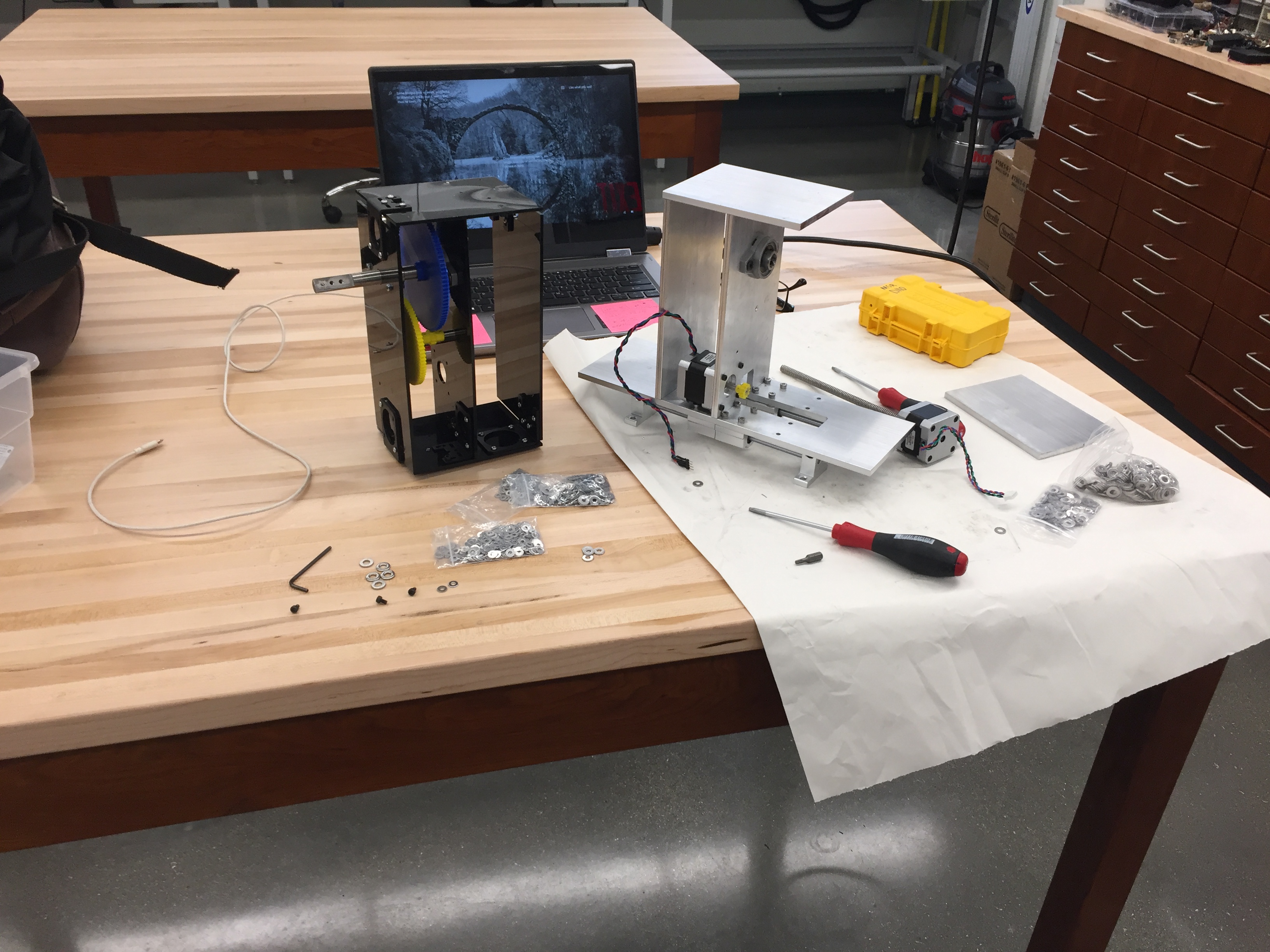
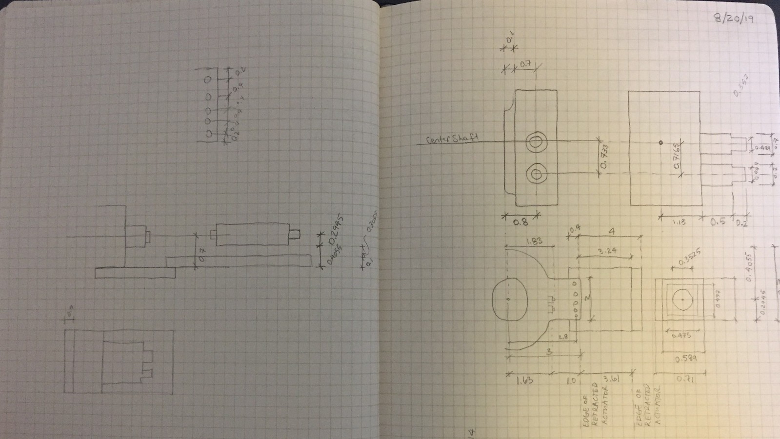
The structure of the instrument is made of aluminum to transfer the loads to the ground. Further development should focus on an insert that receives the control head and the instrument, which is fed through the biopsy port.
- Develop the “instrument” to conform to the exact geometry of the angulation knobs and air/water/vacuum buttons
- Develop holder for the instrument to be fed through the biopsy port
- Develop mechanism to hold and manipulate the instrument to be fed through the biopsy port
- Develop fastening mechanism
- Build in SAFETY precautions both in software and hardware to ensure the device does not damage the endoscope
- Determine the optimal speed and sensitivity of the buttons for each degree of freedom
- Develop the supporting table for the device
- Trim fat from the structure
- Develop procedure to make the device assume the home-configuration
- TEST the device on the pig in the surgical simulation lab
Product Development Process
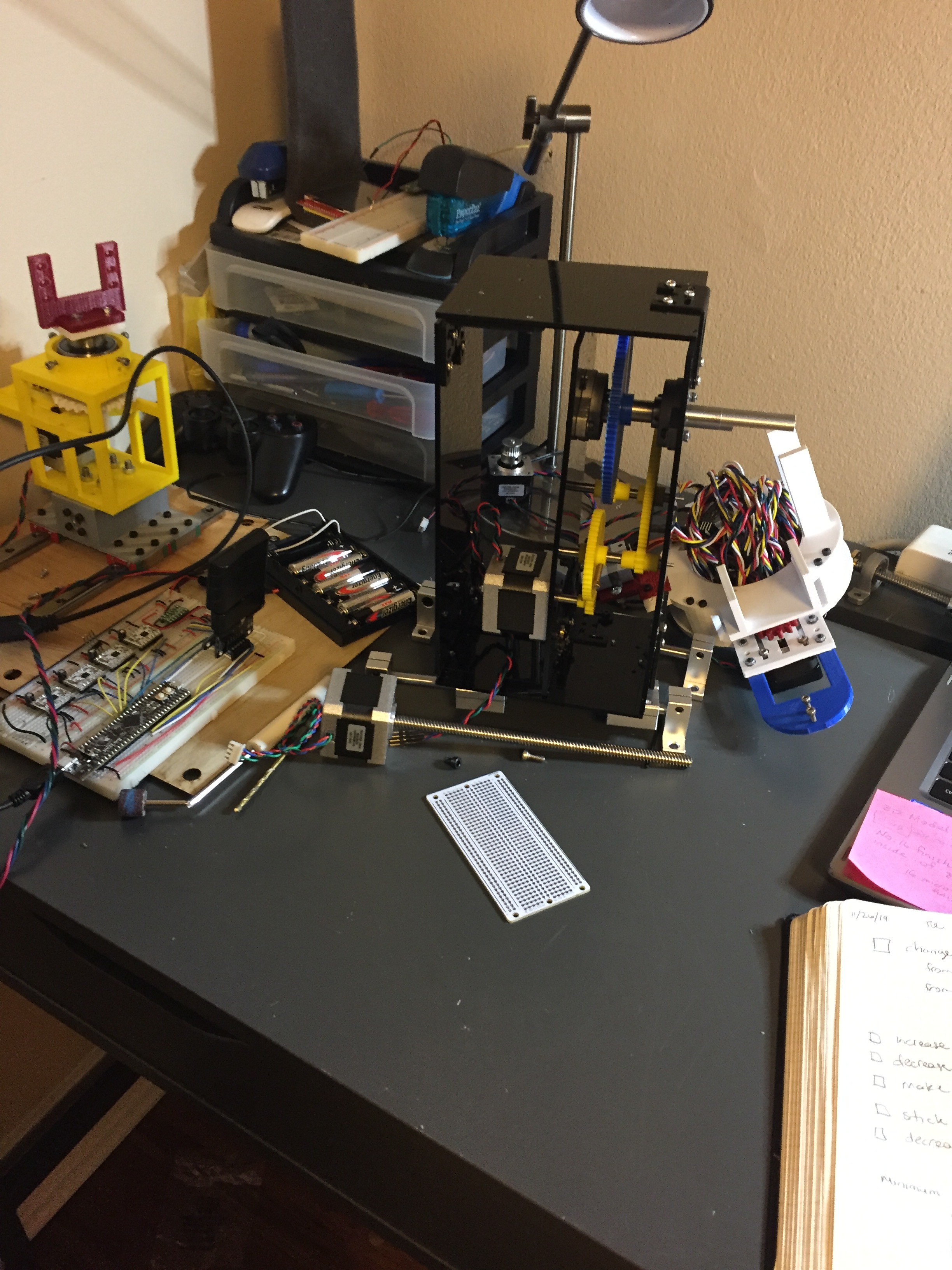
Starting in July and finishing in December of 2019, I developed 2 versions of the prototype.
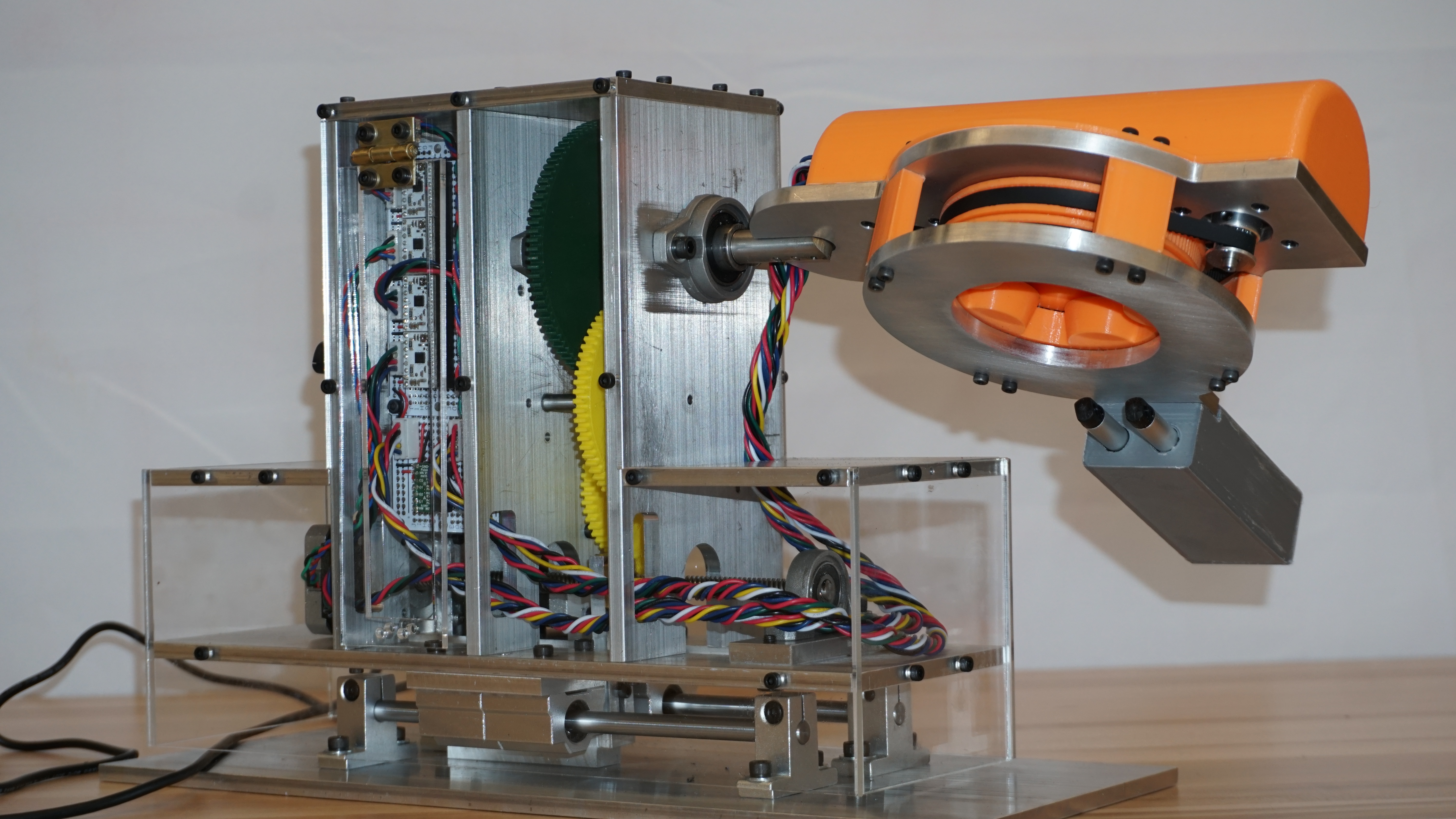
Initially, I focused on the mechanisms that are required to produce the desired motion, while simultaneously sourcing the required actuators and gaining control through code and electronics, one-element at-a-time. Once I built the entire device, capable of producing the desired motion, I developed the firmware to control all of the actuators with a handheld joystick in the desired manner. Lastly, I redesigned the entire device, considering intuitively the dynamics, the structural loads, the smoothness of motion and speed, the packaging of electronics and the overall aesthetics to receive further development in the future. The redesign consisted of the following:
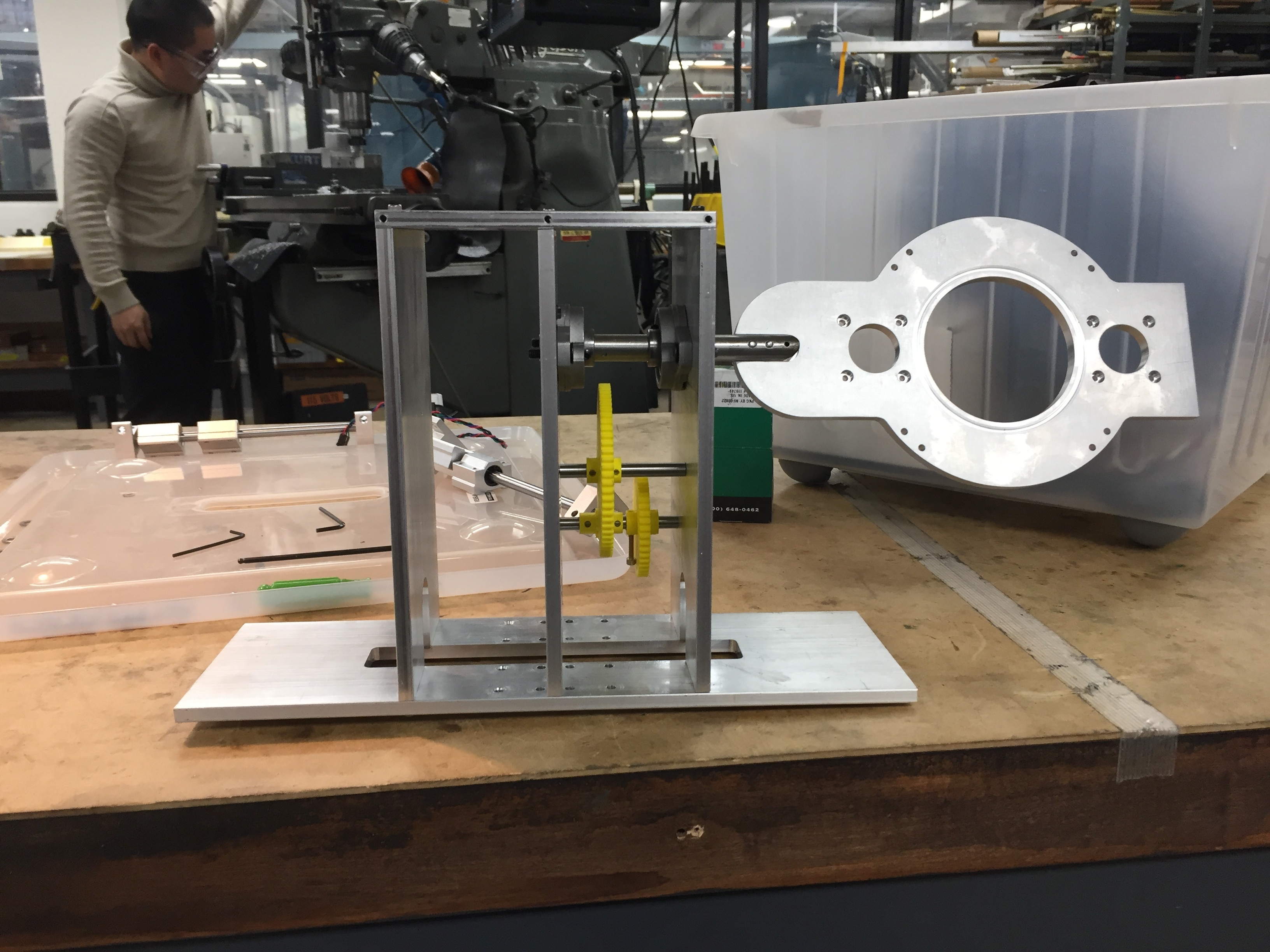
- Fully functional prototype made of metal – considering structural loads from the cantilevered structure
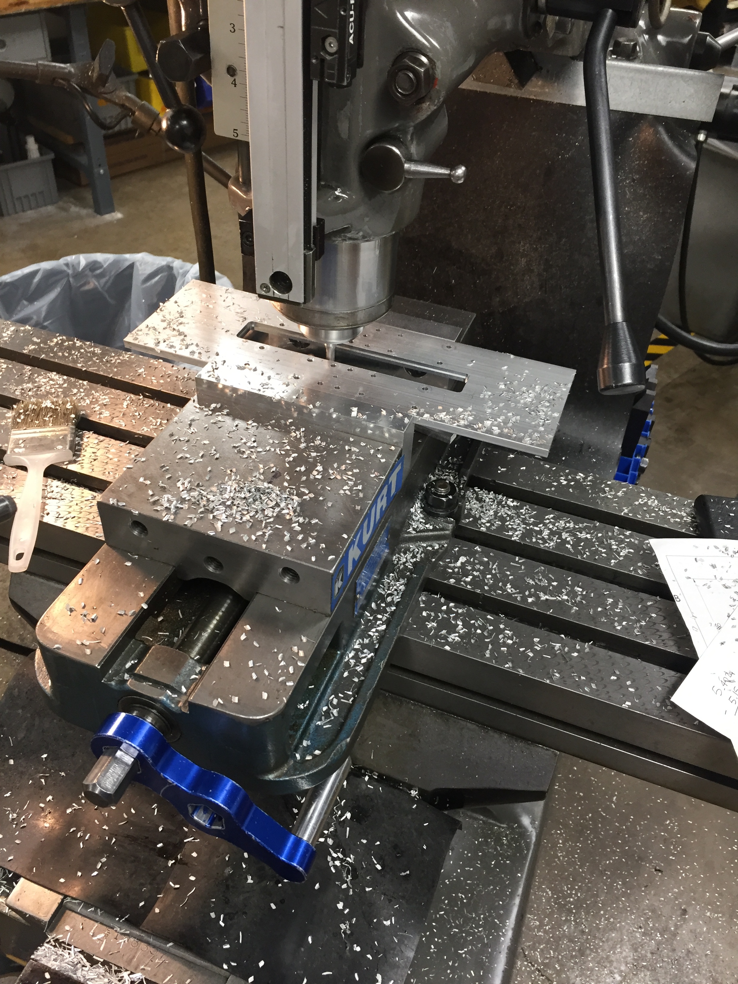
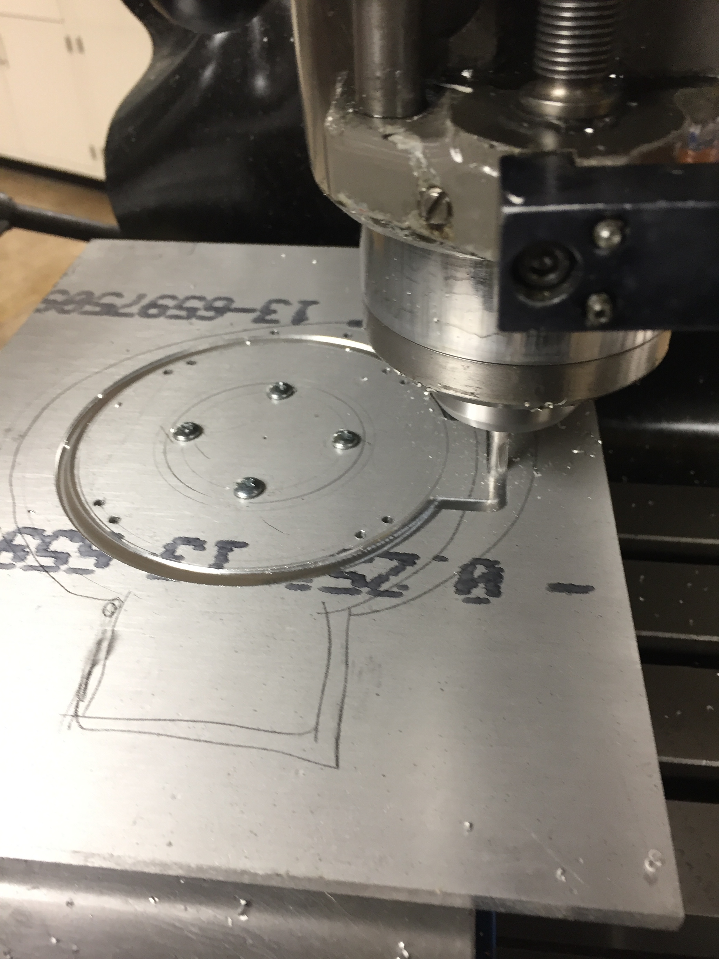
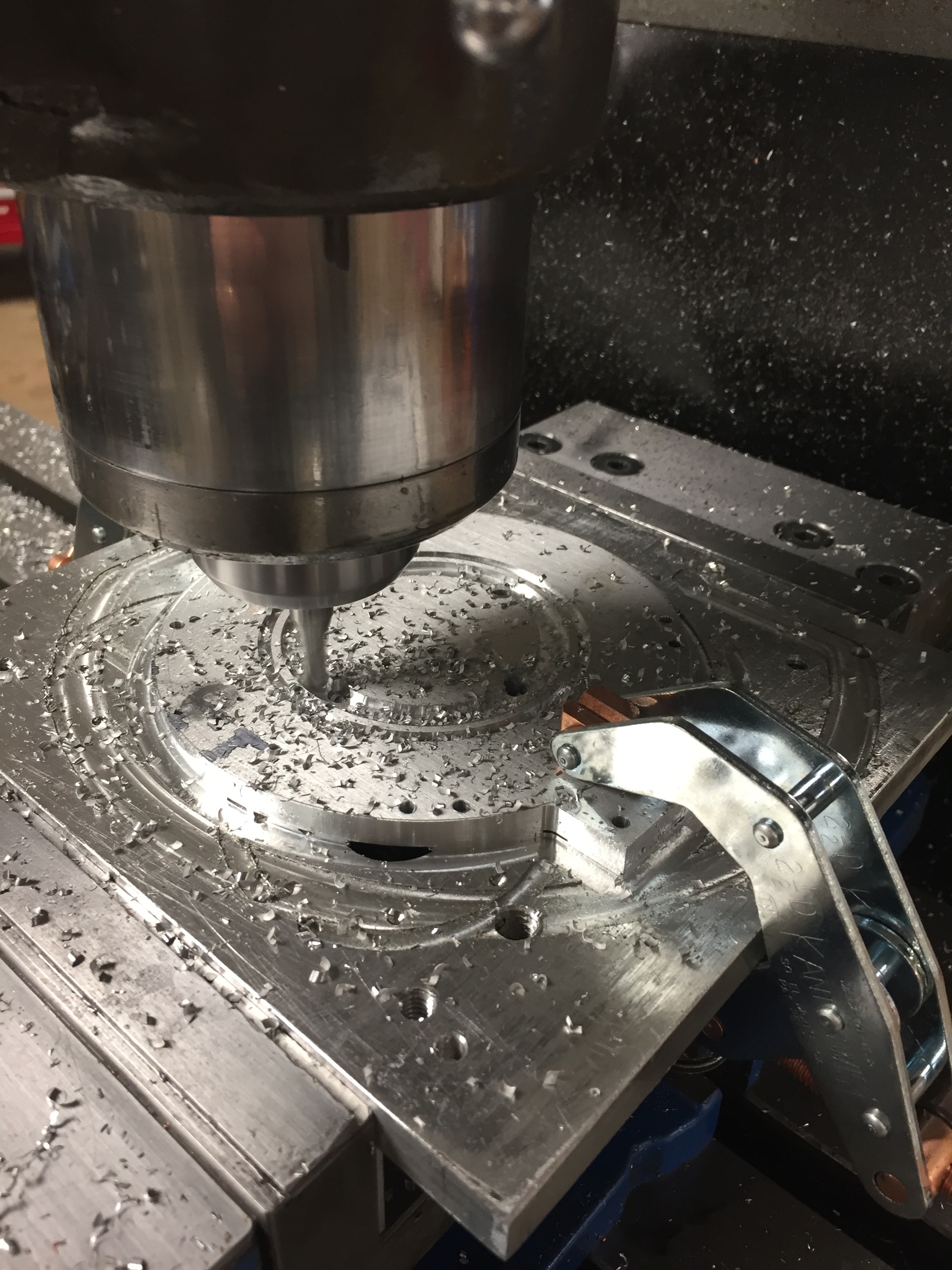
- Worked directly with the machining instructor to fabricate 16 parts from metal using 2-axis CNC, milling machine and lathe, taking note of the feeds and speeds, and techniques
- Redesigned majority of the assembly in SolidWorks (OnShape previously)
- Completed all firmware – all 6 actuators are controlled by PS2 controller – mapping the analog stick displacement to the velocity of the motor
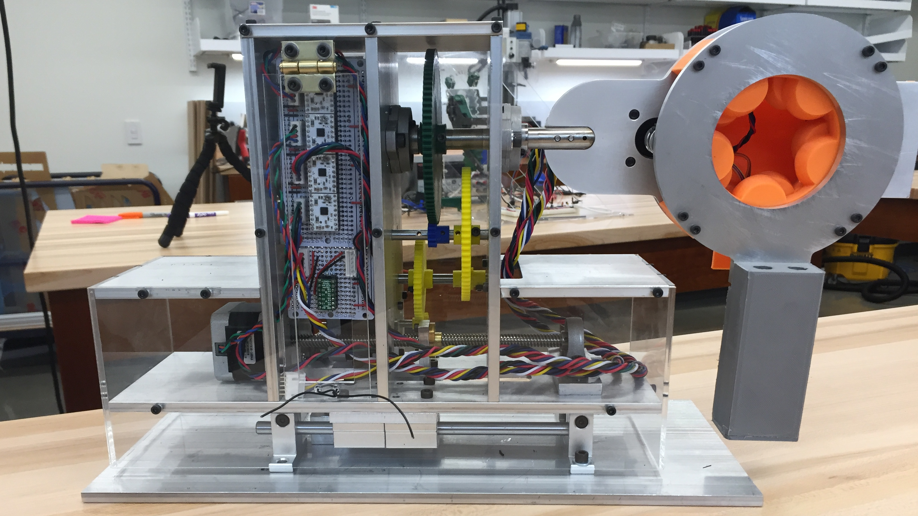
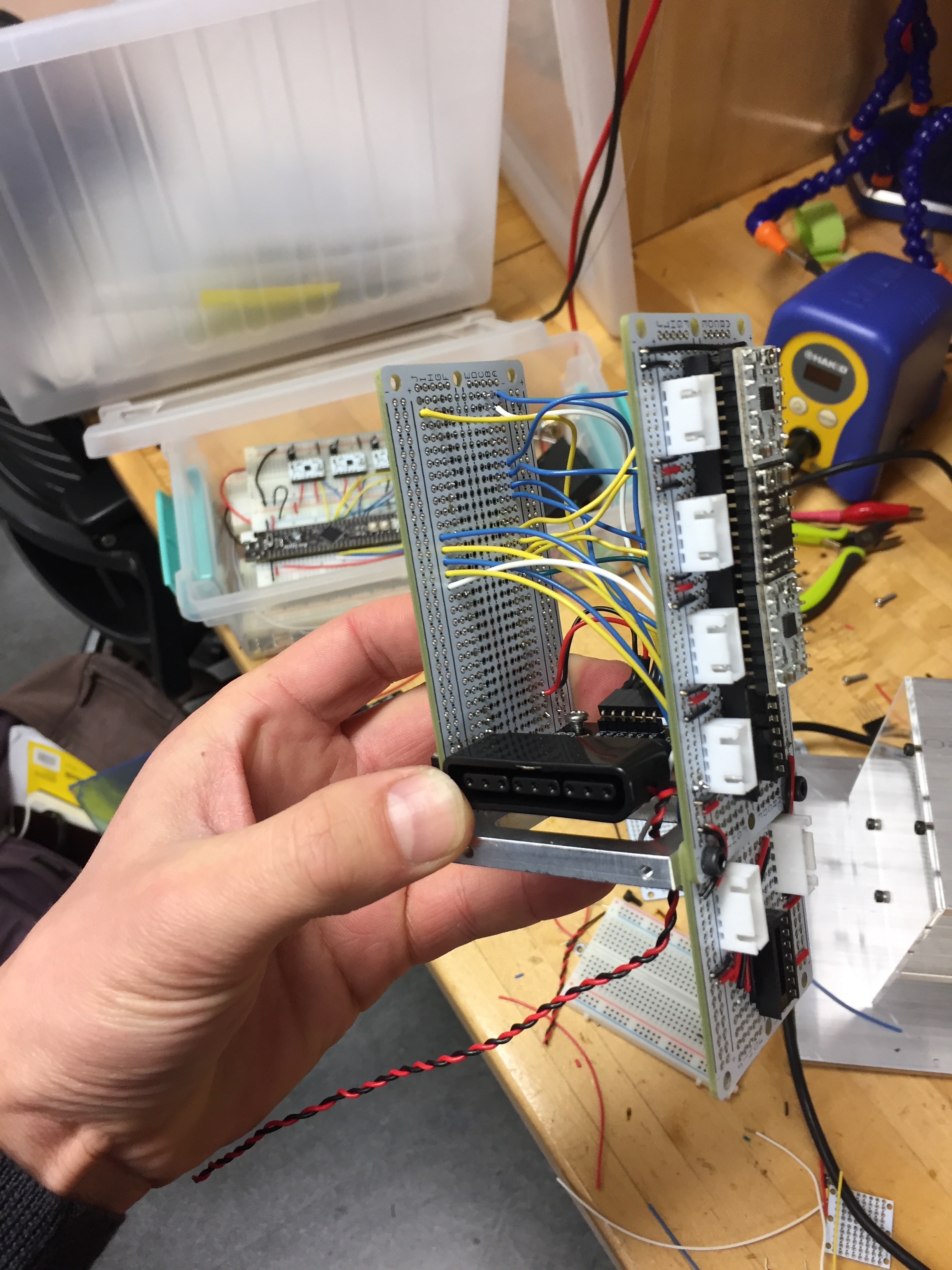
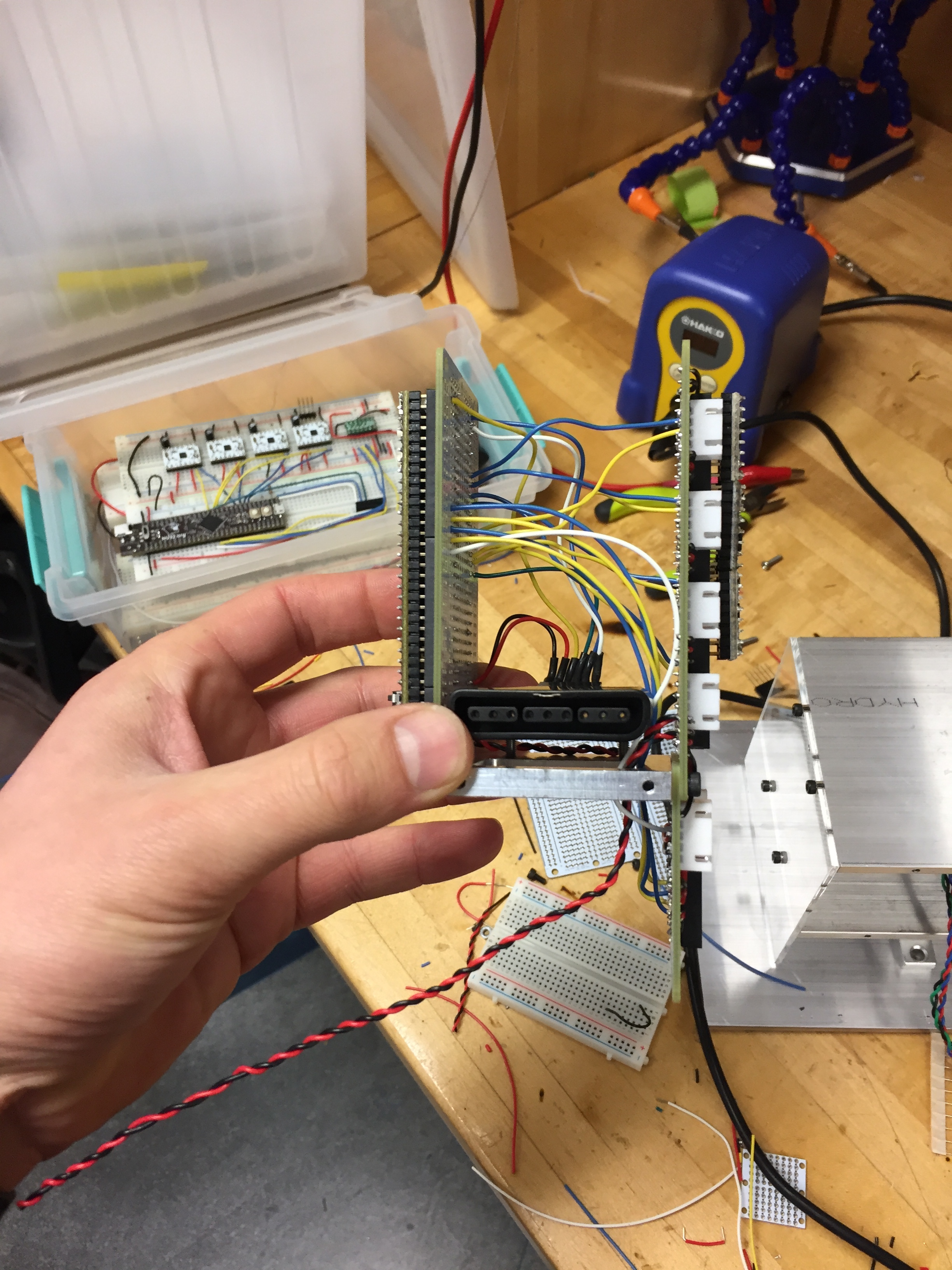
- All electronics are enclosed and nearly packaged inside the structure – no loose wires!
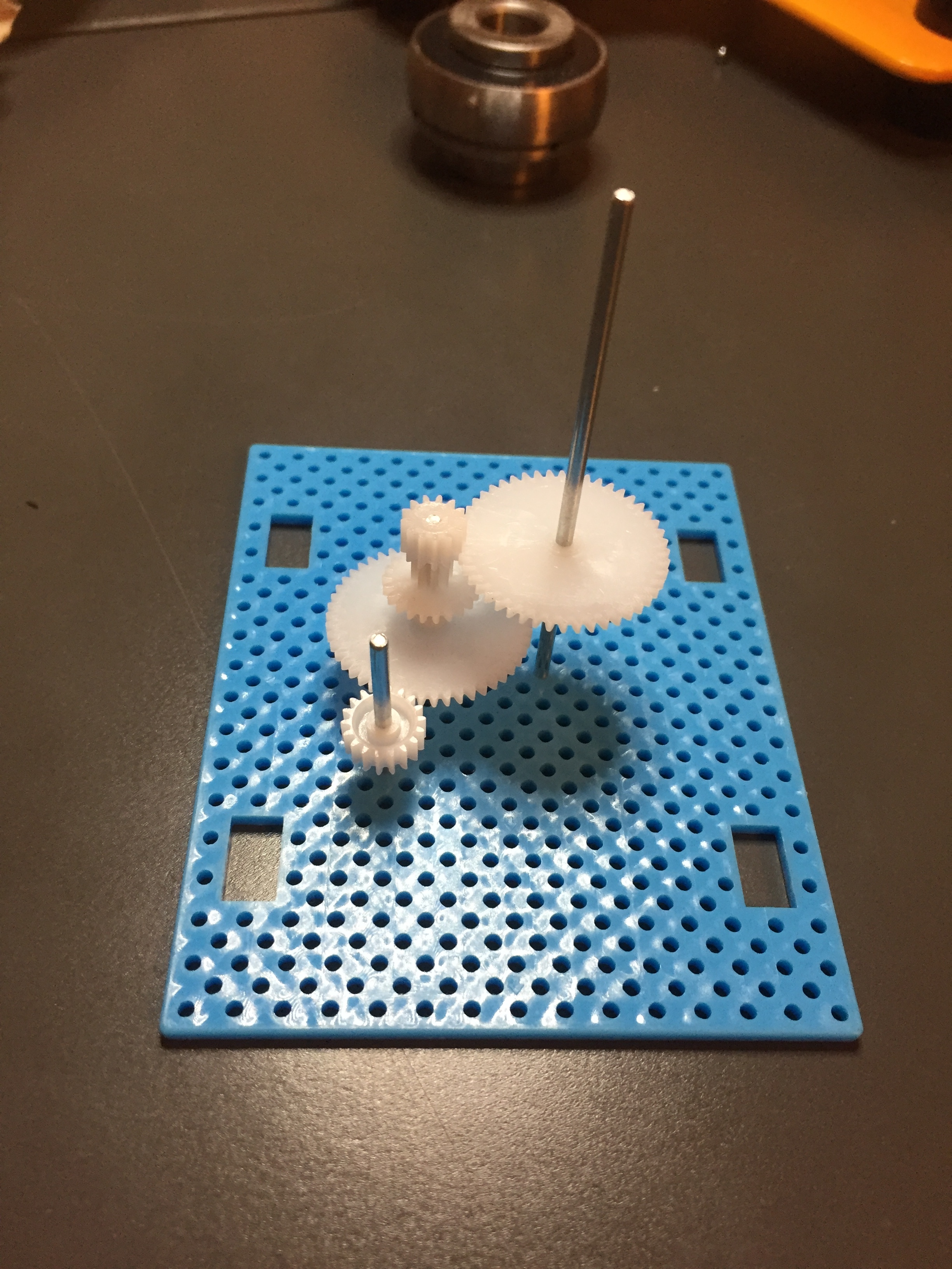
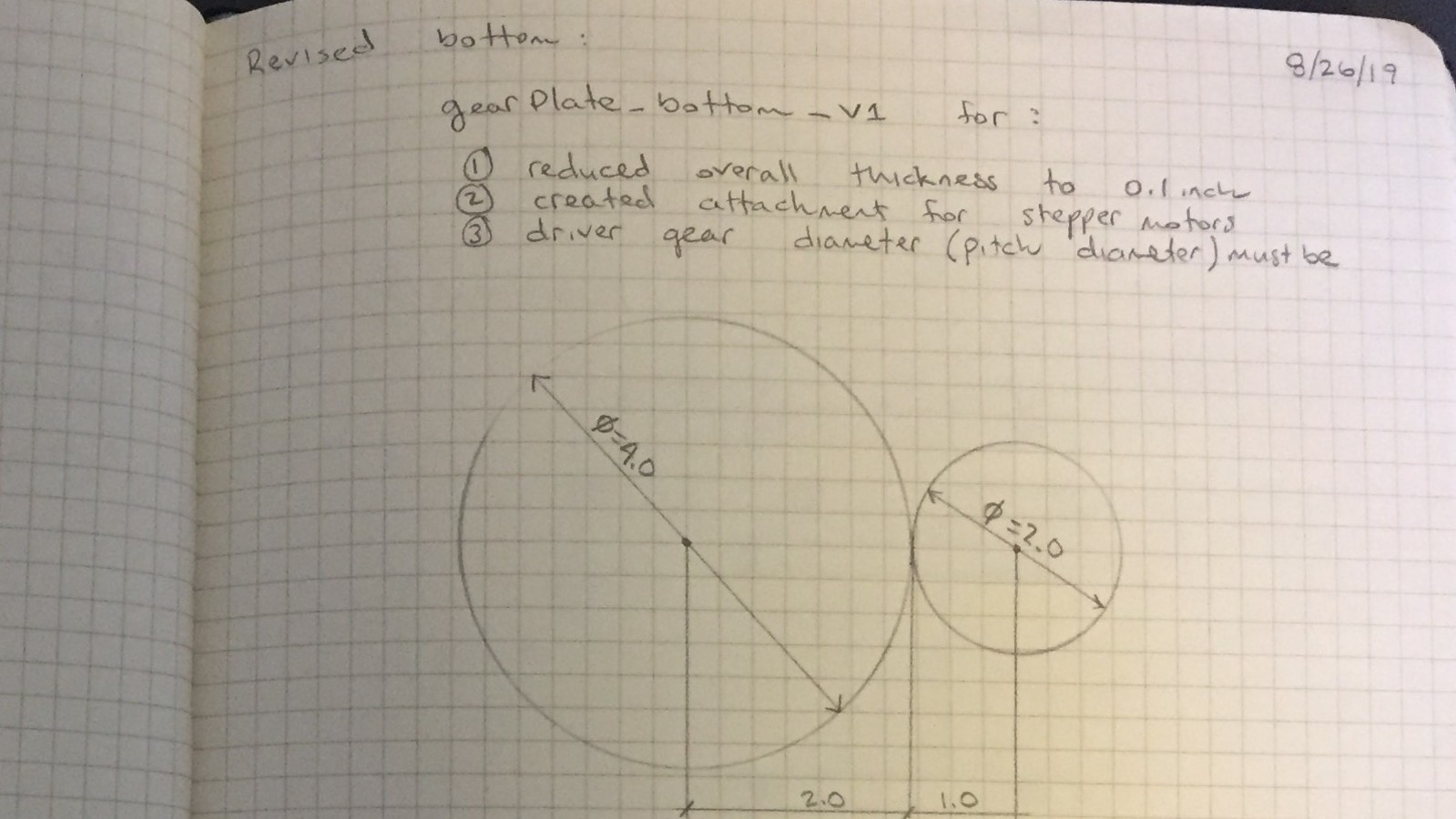
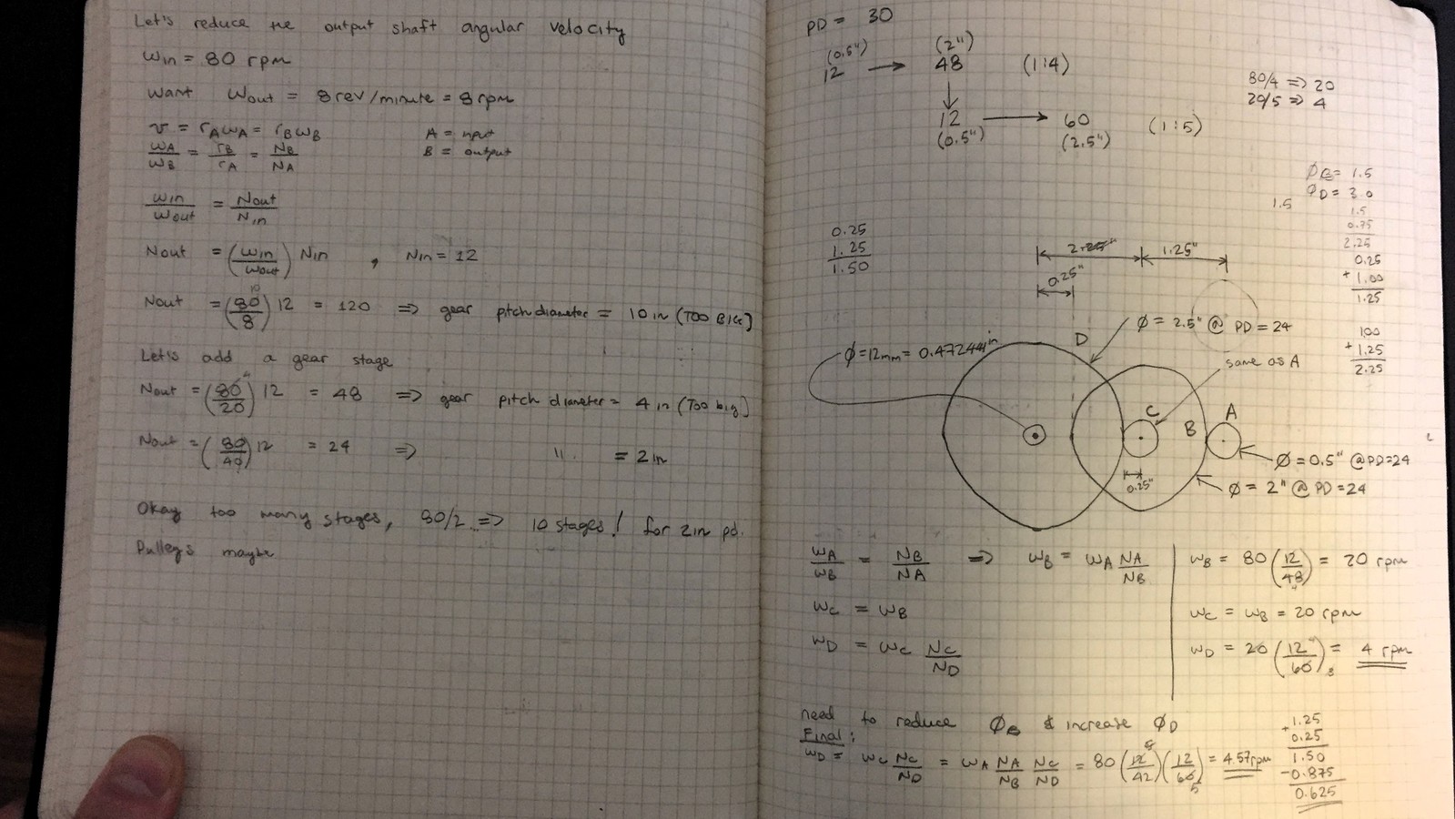
- Created a 3-stage gear train with 1:180 gear ratio, for max holding torque of 666 kg-cm at the cantilever transfer shaft (connection between “instrument” and the device body)
- Revised instrument’s transmission of rotational motion from gearing (1:4 ratio) to belt-and-pulley (1:5 ratio) to reduce backlash and provide a smoother motion
Mechanical
Instrument
I broke this problem into two parts - the instrument and the body. The instrument will hold the control head and the biopsy instrument, rotating the angulation knobs and pressing the air/water and suction buttons - controlling a total of 4 degrees of freedom. Meanwhile, the body holds the instrument, houses the required electronics and controls another 2 degrees of freedom.
Angulation Knob Manipulation
The most geometrically complex problem was the angulation knob manipulation. These knobs control the steerable tip at the distal end, through wire cable. So, when you rotate the angulation knob, you’re essentially winding the cable around a drum, which in turn pulls on the tip in the desired direction. There are 2 degrees of freedom: Up and Down, Left and Right. In total, there are 4 knobs to control, but 2 of the knobs are angulation locks - their job is to lock the cable drum in the desired position.
I attacked this challenge first and it took me the most amount of time. I did not want to turn this project into a CAD modeling exercise, and, frankly, I am not sure I would have developed my design with CAD alone. So, I focused on visualizing the geometry through building the endoscope’s control head from cardboard, acrylic - basically, anything I could quickly get my hands on. I literally played with simple mechanisms over-and-over.
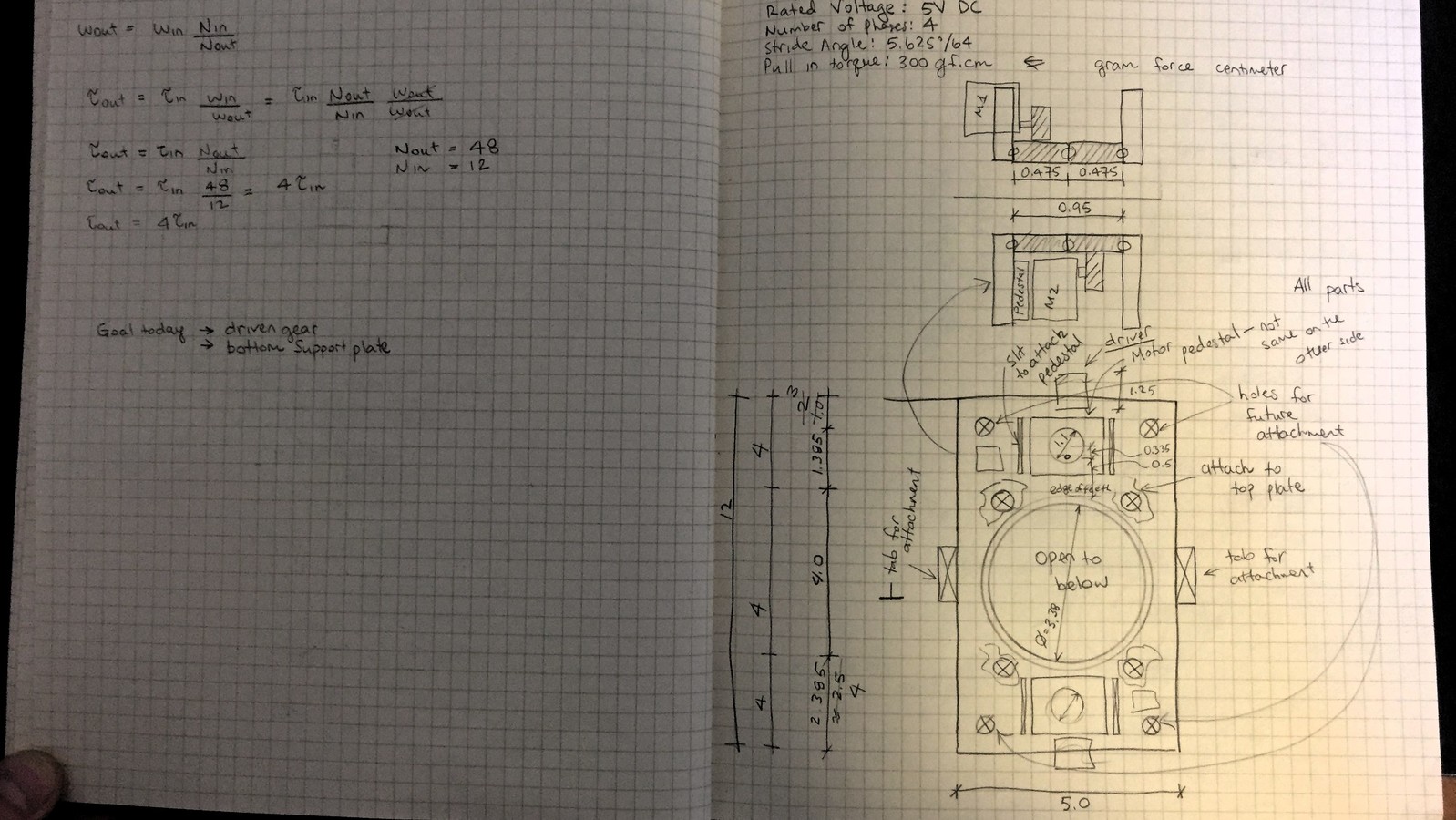
In the process, I realized that by using the stepper motors, I could eliminate the need to control the angulation locks, because when the stepper motor is energized, but not engaged to produce motion, it will hold its position - in fact, you can look up the holding torque of this motor and use that info to size the motor for your application. Thus, there are only two motors.
Of course, I haven’t told you about the juicy part yet, which is the mechanism to rotate the angulation knobs. I needed to transmit the rotational motion of the motor to the rotational motion of the angulation knob. But, its not one knob, it’s four, well two. Also, how do I easily mount and dismount this control head to my device? Do I need to create a sandwich of some sort? This took awhile and this is where playing with “cardboard” really paid off.
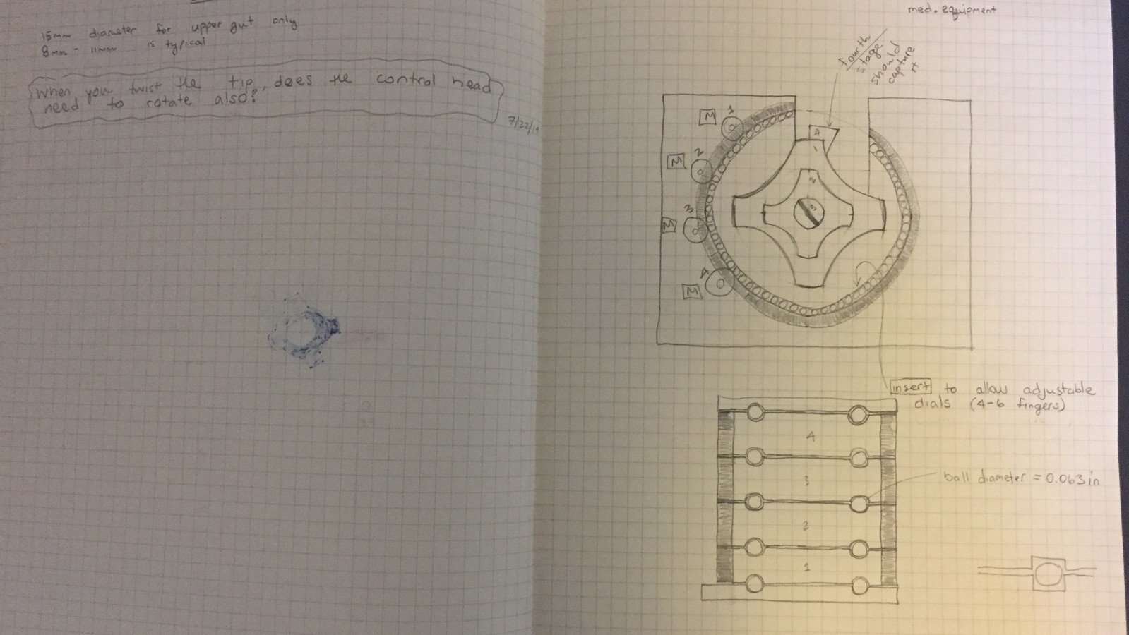
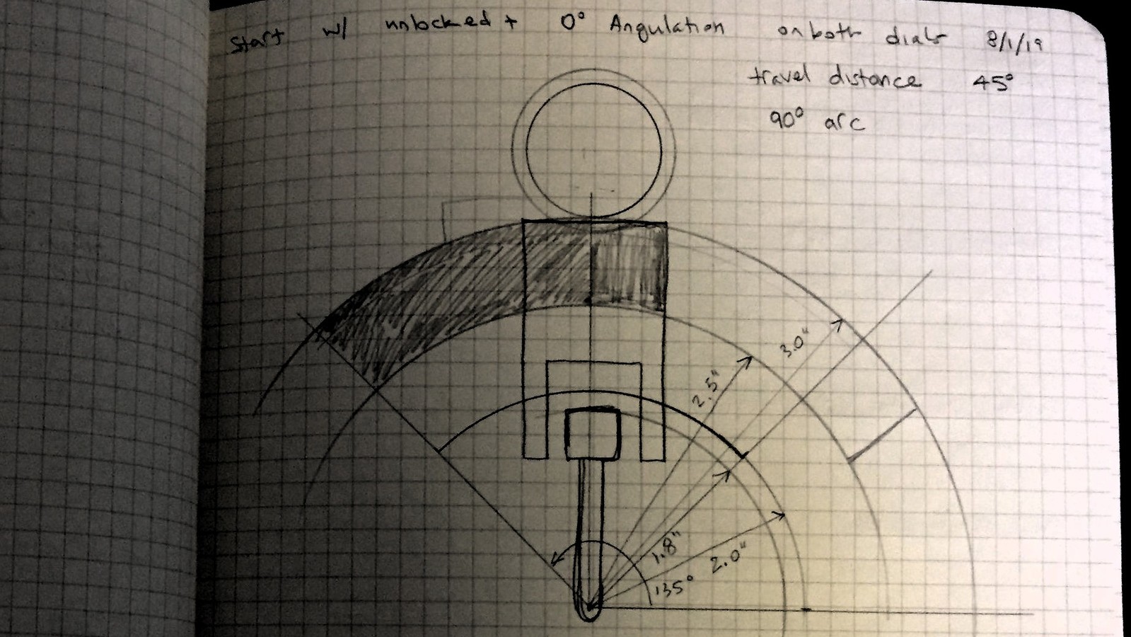
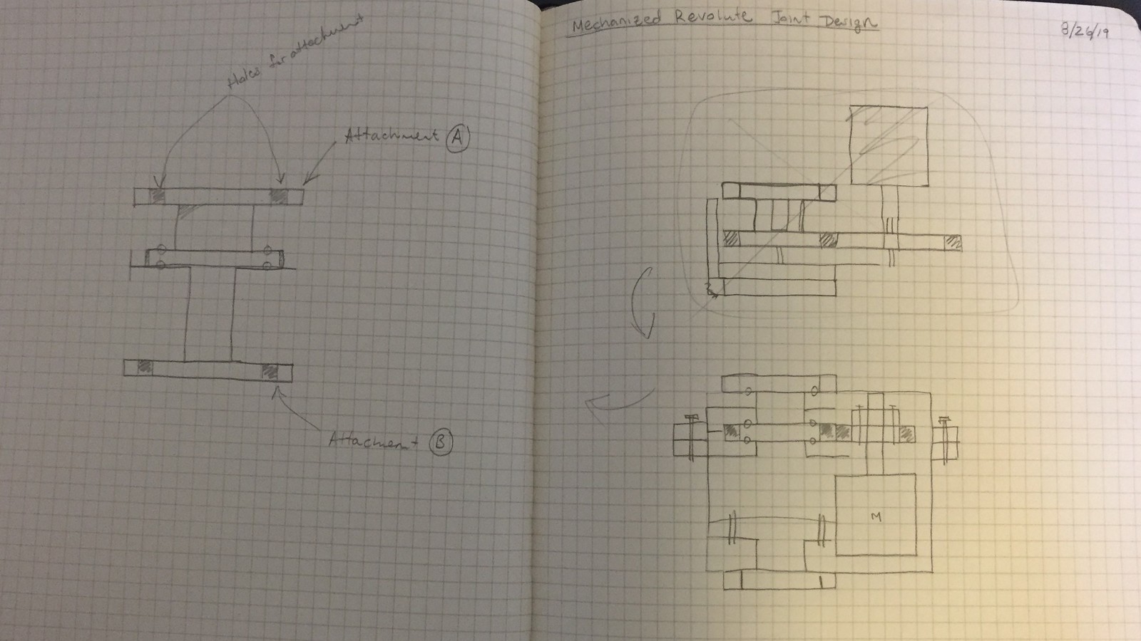
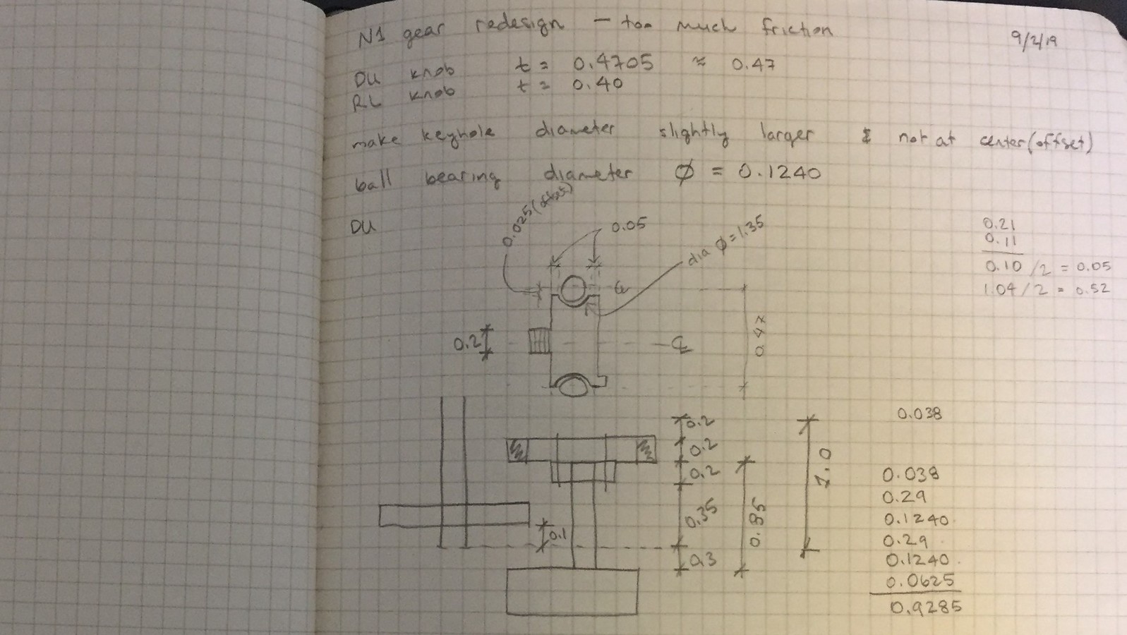
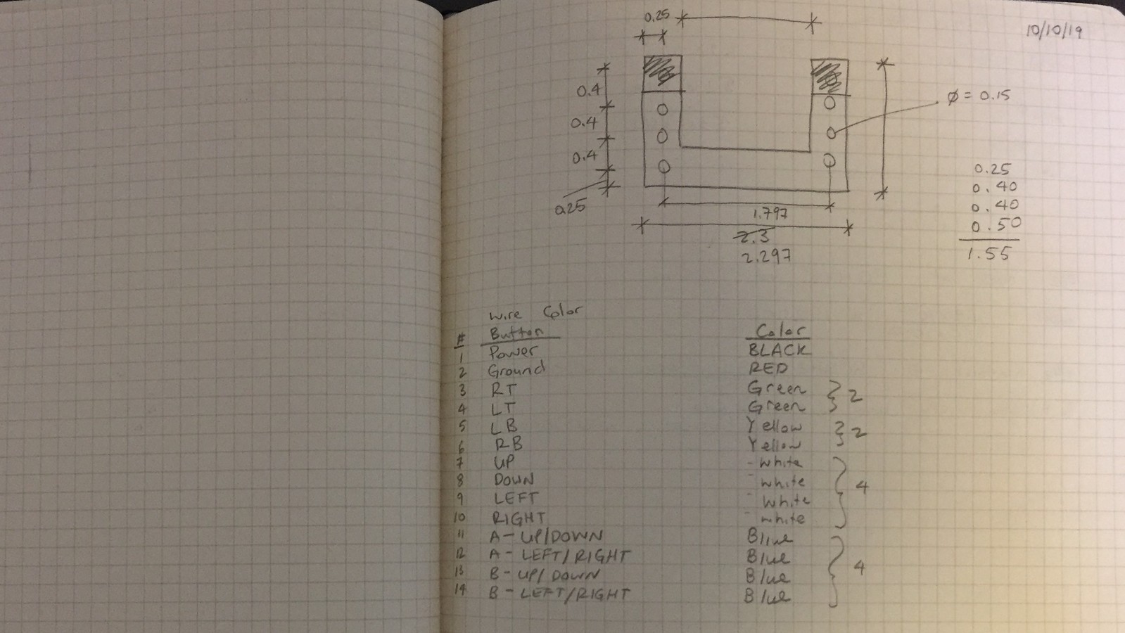
I decided to mount the control head, facing into the device - so, my device would swallow up the angulation dials and on the backside, I would use a simple fastening mechanism. Each angulation knob has a different geometry and different range of angular displacement. For example, the Up/Down angulation lock is located closest to the body, but looks like a pin (skinny), rotating only about 30 degrees. Next, the Up/Down angulation knob has the largest diameter and thickness, making 5 and 4 full rotations in the clockwise and counterclockwise directions, respectively. Next, Right/Left angulation knob has its own diameter thickness and displacement. Lastly, the Right/Left lock also only rotates a fraction of a revolution.
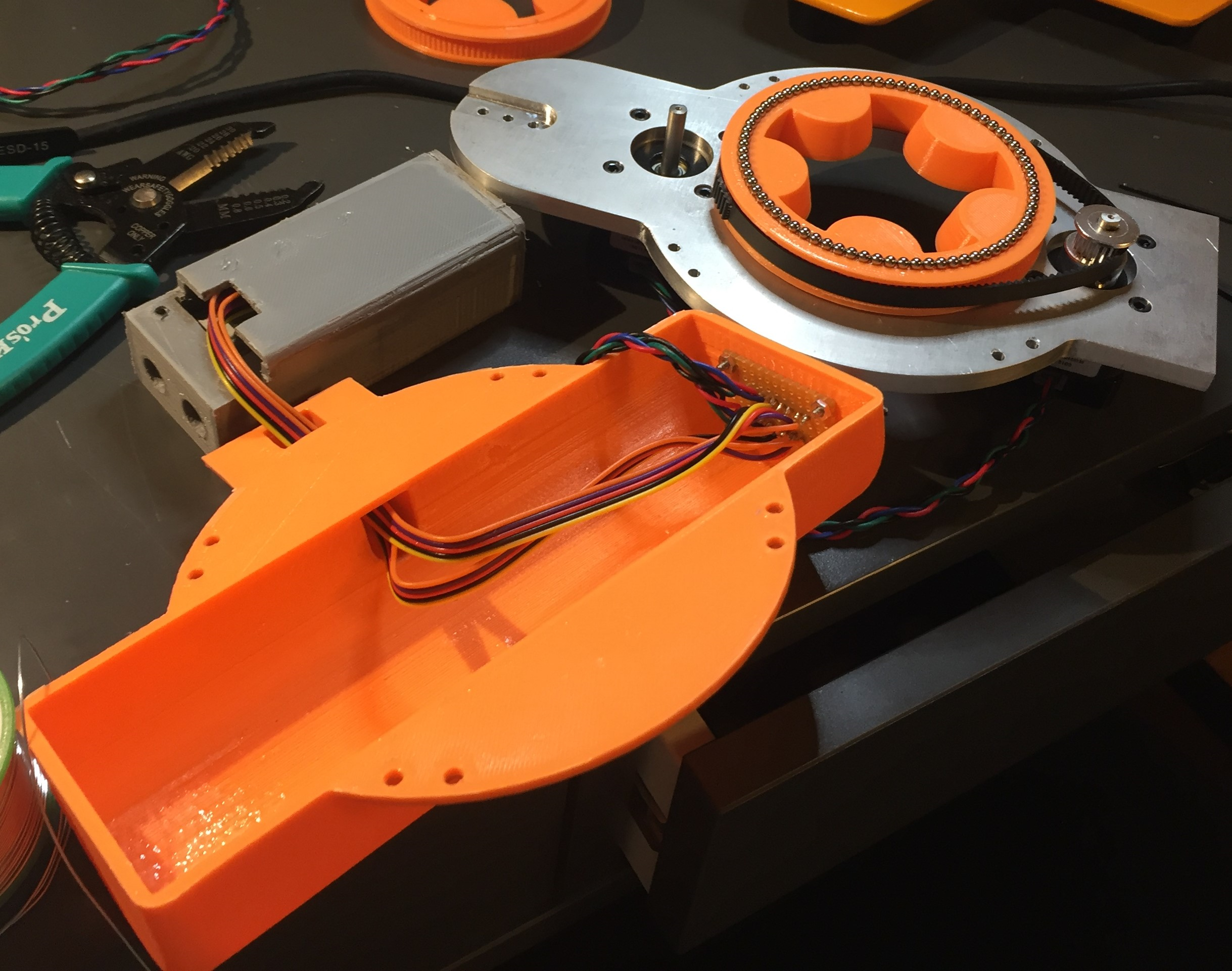
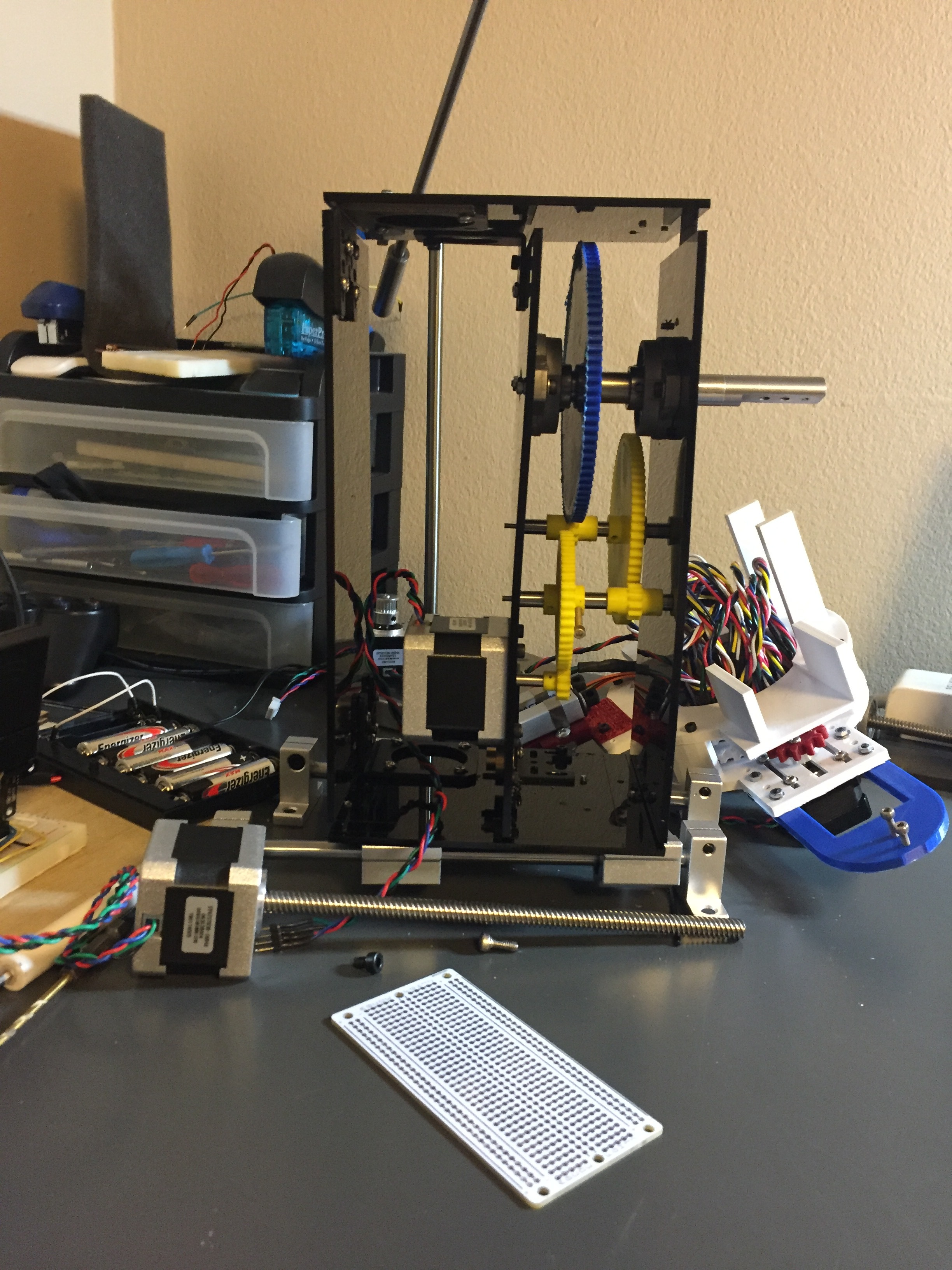
So, the angulation knobs are inside and this is where the beauty (at least to me) of my design comes into play. To transmit my rotational motion, I used a hollow gear that: A - on the inside, receives an insert that conforms to the exact geometry of the angulation knob, B - the gear rests on either the other concentric gear or the top/bottom surface (enclosure) via spherical balls (ball bearing) - there is a groove in each gear. The motor spins this gear, well sprocket now, via belt (similar to 3D printing - where I got the idea).
Originally, I used gears with a diametral pitch of 12, then to reduce the backlash, increased the pitch to 24, then 36. Ultimately, while 3D printing these gears realized that a belt-and-pulley system might be a better option - something that I could implement quickly without going too far off on the tangent to reduce the backlash and produce a much smoother motion. These refinements were the last to be implemented, because they were not on the critical path, as far as my schedule was concerned.
More coming soon
Please refresh your browser to see 3D Models
Version 2 Assembly in SolidWorks - *partial assembly - full coming soon*
Version 1 Assembly in OnShape
Electrical
Design Approach
Version 1:
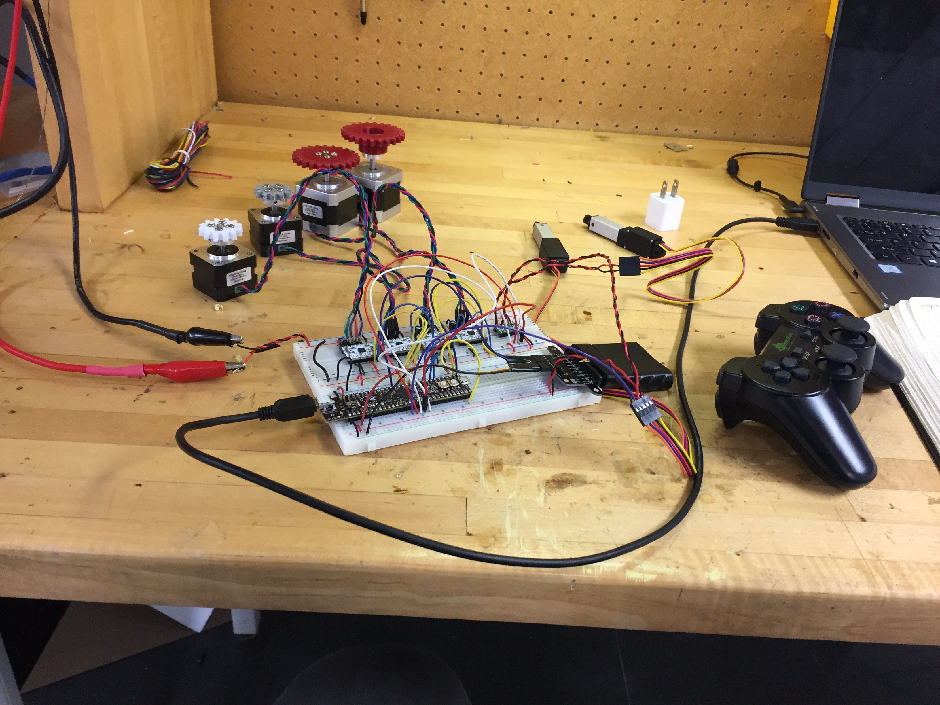
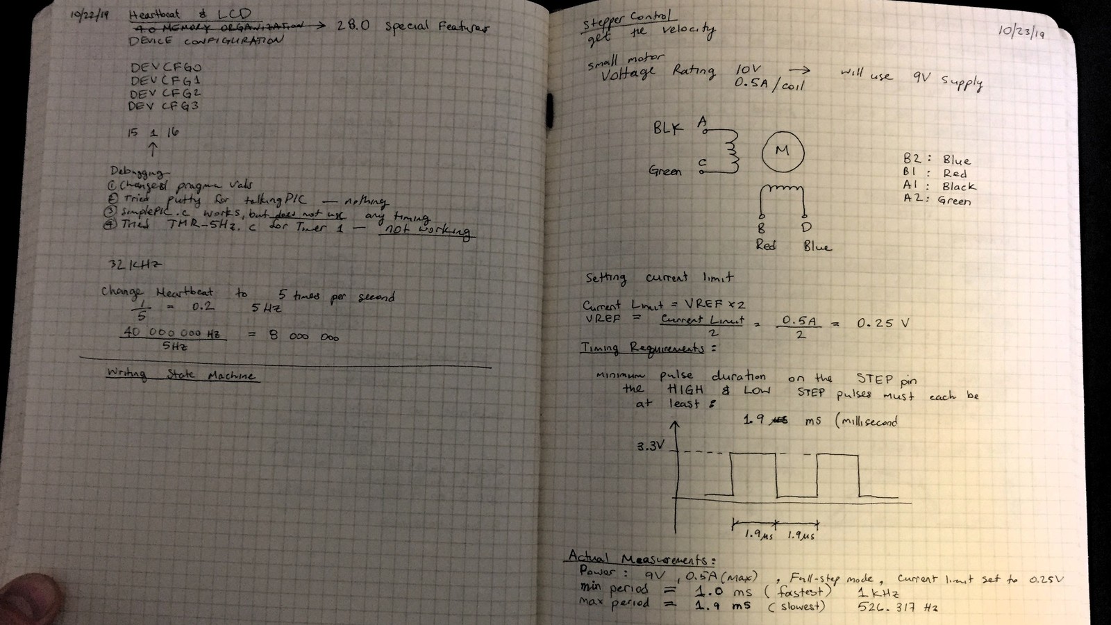
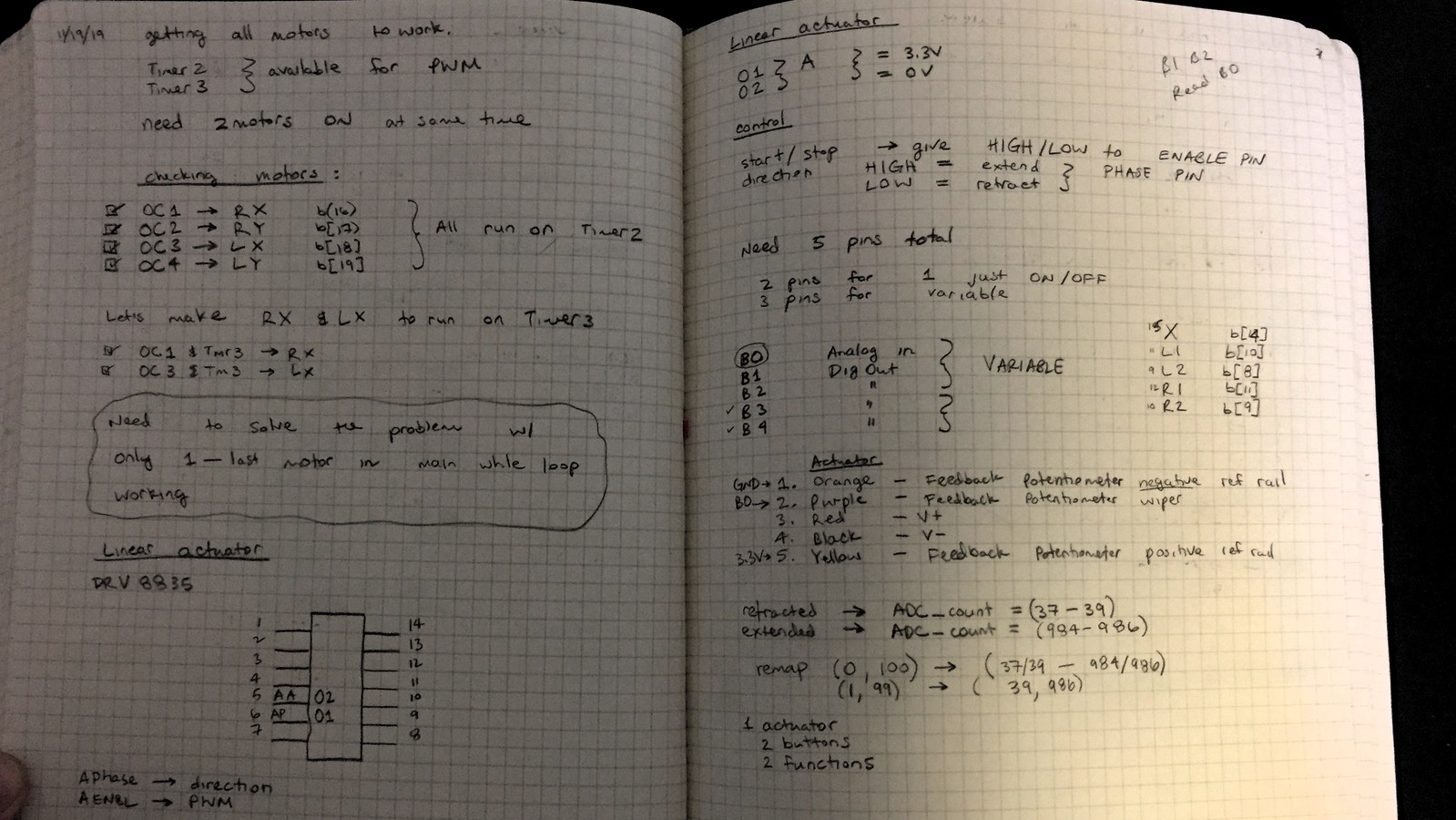
- Rotation: initially used 28BYJ-48 5V stepper motor & ULN2003 driver with push buttons, then upgraded to the beautiful NEMA-14 and NEMA-17 stepper motors & DRV8834 drivers to gain better torque, control and reliability.
- Translation: used micro actuator with position feedback and linear actuator control board, both from Actuonix. The control board was bulky and burned out easily (went through two $40 a pop - way too exensive), but was easy to control using the PWM signal, mapping duty cycle to piston displacement. After burning out the second driver, decided to switch the driver to a double H-bridge ($5!!!!) from Pololu, about 1/10 size of initial driver. Took advantage of the potentiometer feedback feature of the actuator to create a function in code to control the displacement of the actuator.
Version 2:
- User Control: initially used a wired Xbox controller. Due to lack of documentation, did not attempt to tap into the controller with code, but rather I completely gutted the PCB and used it as structural backbone for wired connections to the buttons and the analog sticks - running 12 wires from the joystick to the microcontroller. Tested and debugged electrically, then coded. Ops. Problem! Due to such a large amount of wires, kept loosing electrical connections and had to rewire, clean and resolder…you get the point, at least 3 times. Now, I appreciate a PCB so much! So, the reliability was in question. How could I give this controller to the surgeon without being convinced that it will work! S0, I switched to the wireless PS2 controller and wrote a driver for it. Boom! Only 4 wires needed - not 12! Reliability, please. Works every time! Did I mention, the 8 analog reads that the microcontroller required to do to determine the displacement of the sticks, while the microcontroller can do one ADC conversion at a time. Talk about a speed killer!
Circuit Schematic
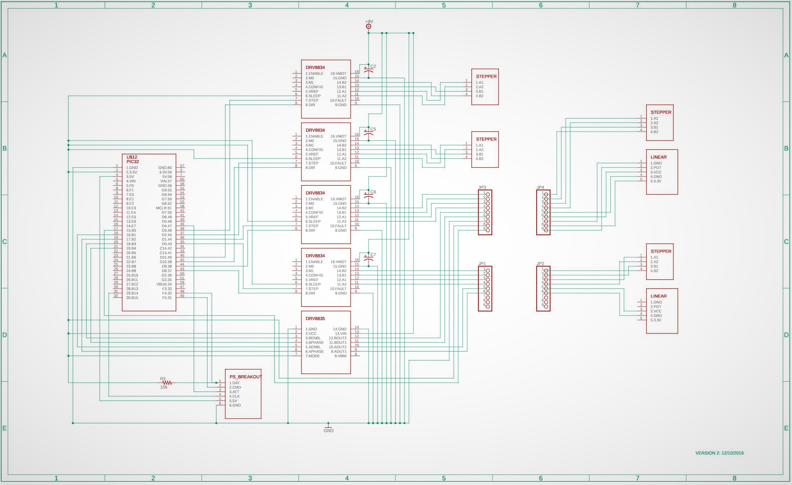
Components:
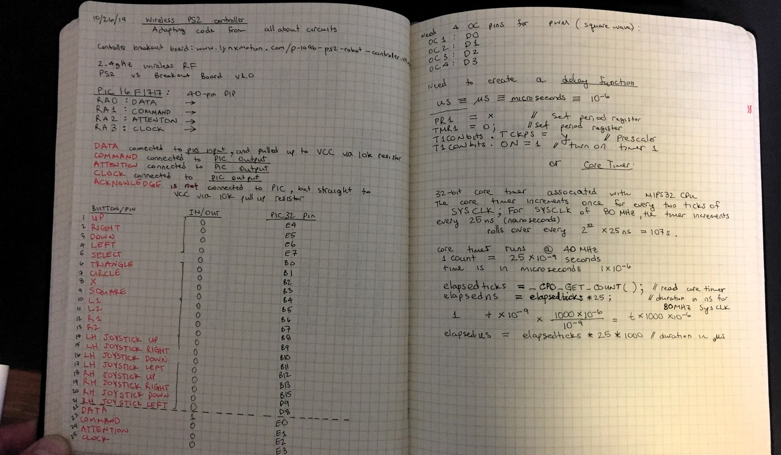
- PS2 wireless controller w/ breakout board
- NU32 PIC32 microcontroller
- Driver for linear actuators - DRV8835
- Driver for stepper motors - DRV8834
- NEMA 14-size hybrid bipolar stepping motor
- NEMA 17-size hybrid bipolar stepping motor
- NEMA 17-size hybrid bipolar stepping motor w/ integrated 7″ threaded rod as its output shaft
- Micro Linear Actuator with Position Feedback
- 9V, 5A power supply
- 10k Resistor
- 5V, 0.5A power supply
Retired Components:
- Xbox 360 Wired Controller
- Linear Actuator Control Board
- 28BYJ-48 5V stepper motor
- ULN2003 stepper motor driver
Software
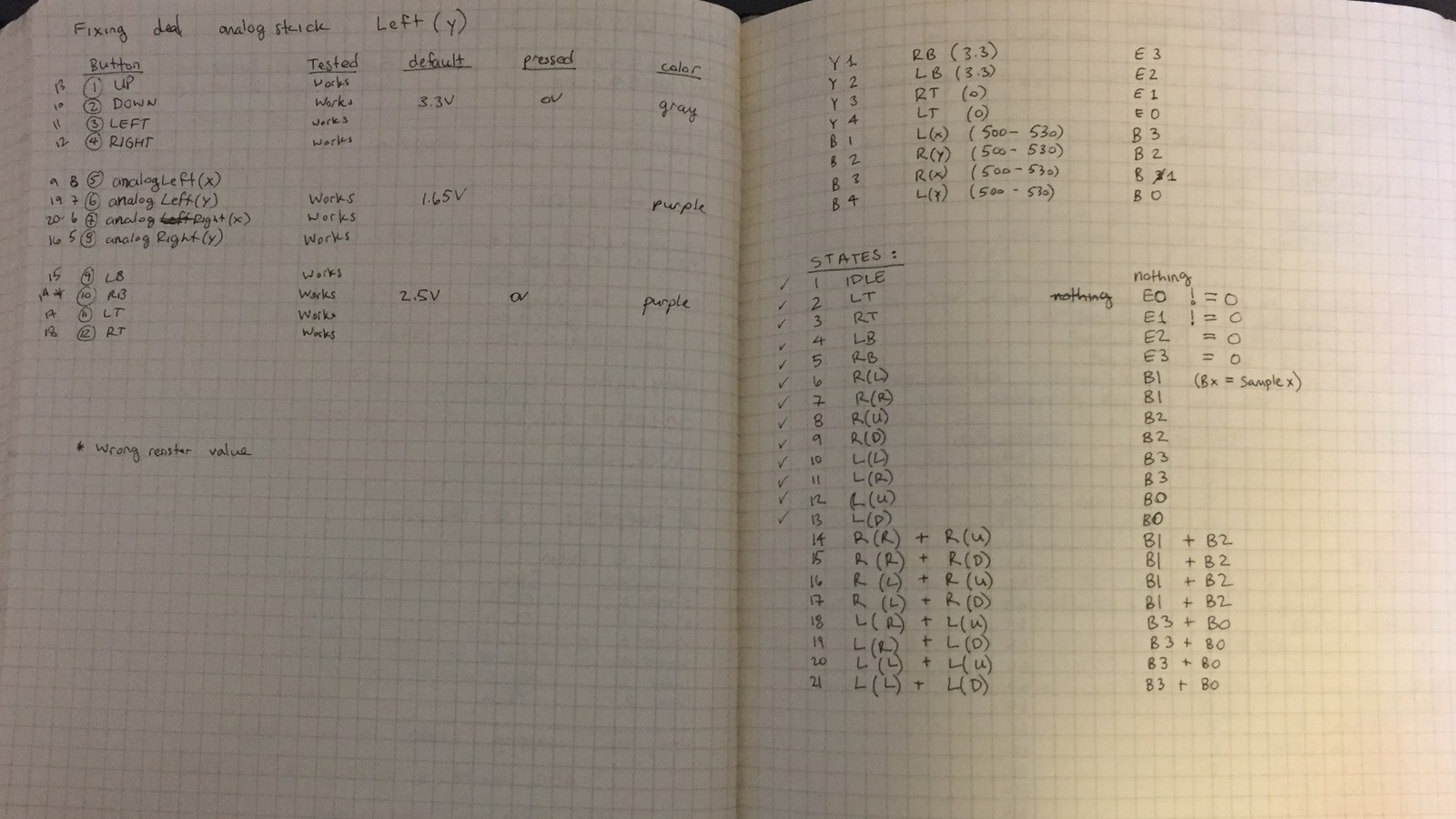
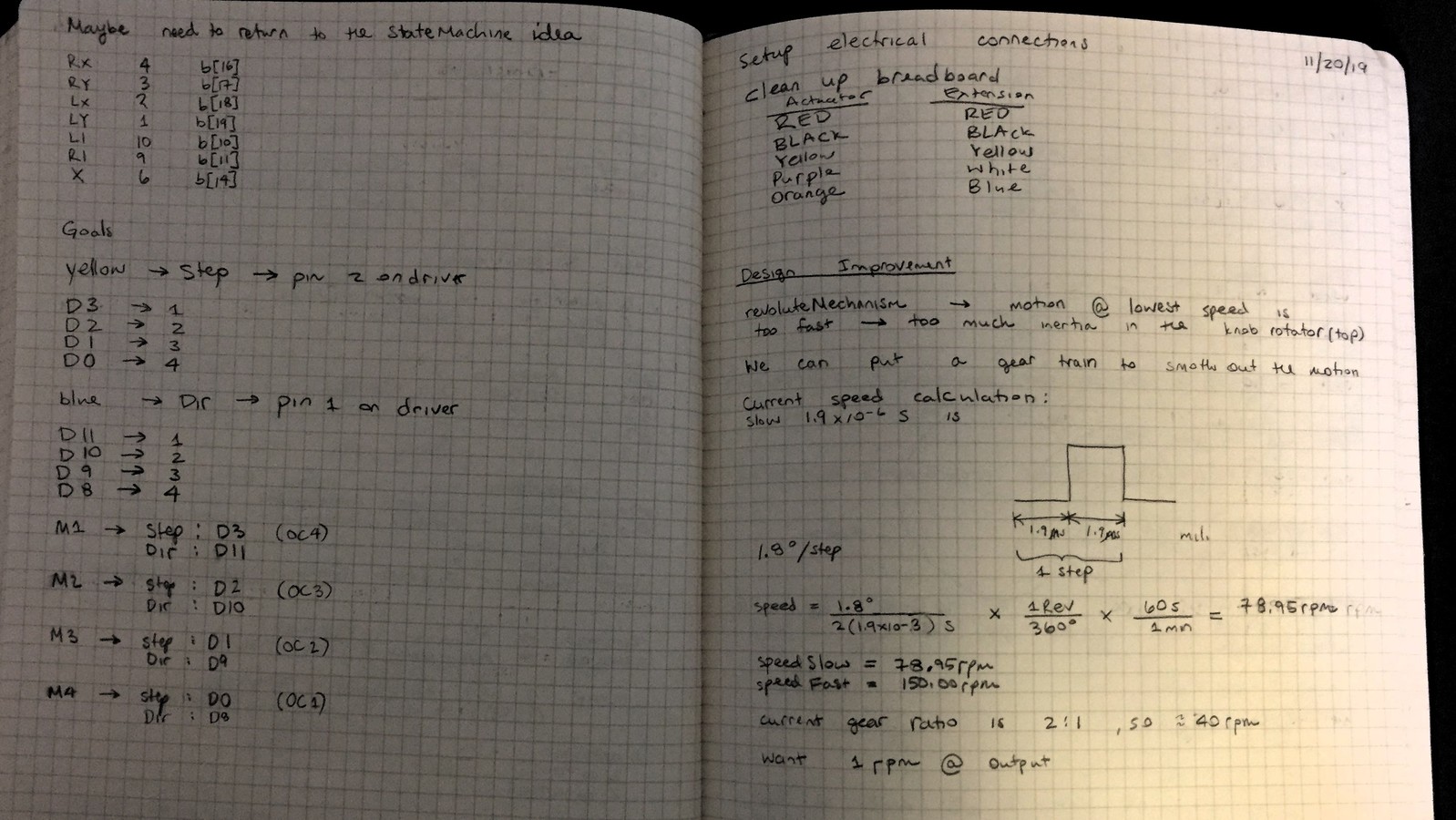
I wrote all firmware in C to function on the NU32 PIC32 microcontroller, specifically the PIC32MX795F512H. I structured the software to run as a FINITE STATE MACHINE. Each button press or analog stick displacement corresponds to a STATE. To modularize my code, I wrote a separate driver for the handheld controller, the stepper motor and the linear actuator, as well as additional library to contain helpful functions. The mainline code monitors the state and produces the appropriate response for that state.
Velocity Mapping
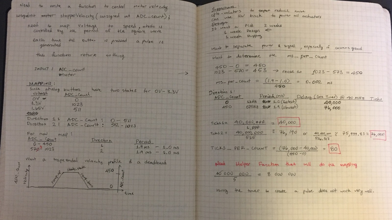
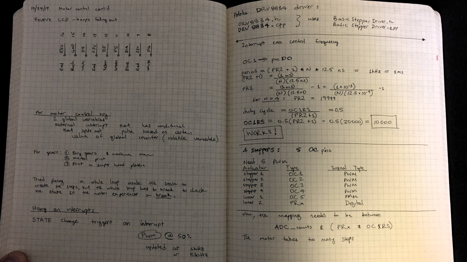
Dr. Hedberg wanted to control the speed of the motion of the tip. The most intuitive way to control the speed is to map the analog stick displacement to the angular velocity of the motor. There are two ways of controlling the speed of the stepper: (1) control the resolution of the step (i.e. microstepping) and/or (2) varying the period of the square wave. I implemented both.
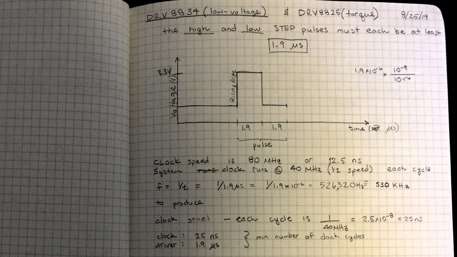
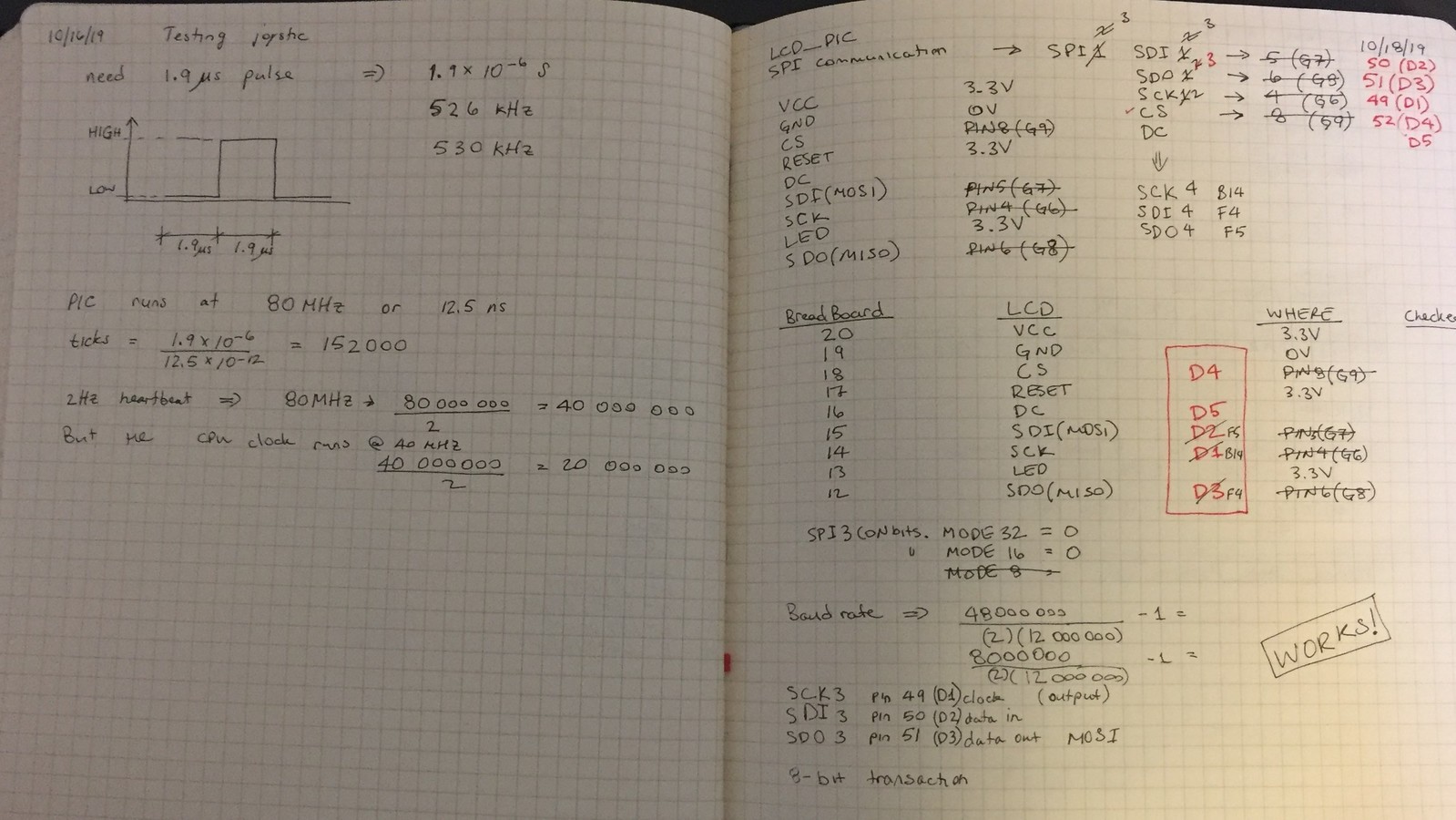
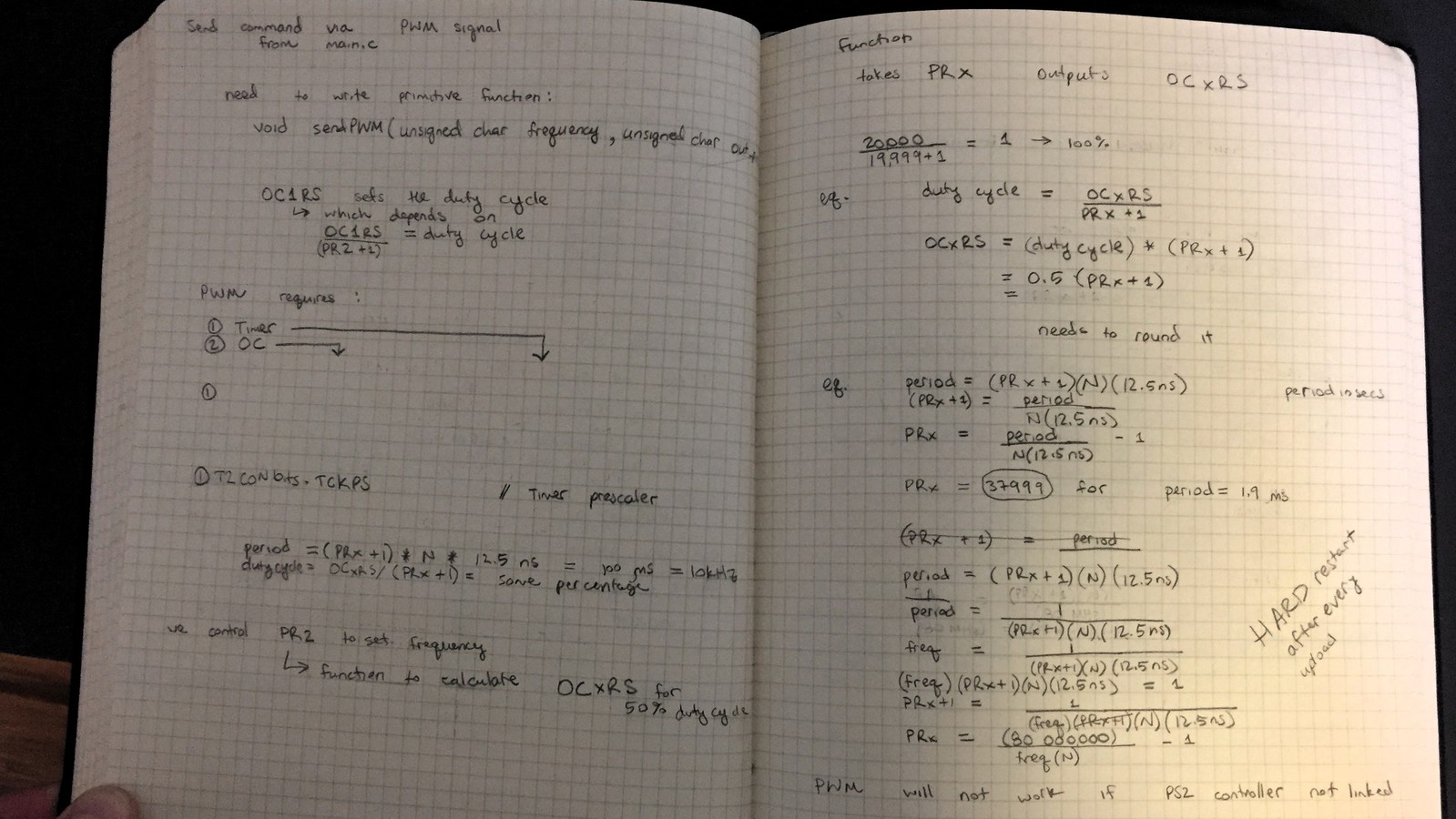
I picked the drivers that were easy to work with, specifically the DRV8834. At the basic level, the driver expects two input signals: (1) digital for direction and (2) square wave for the speed. From the data sheet, the maximum period for the square wave is 1.9 milliseconds (526 Hz) - corresponding to the slowest speed. Using the lab’s waveform generator, I determined the minimum period for the square wave to be 1.0 milliseconds (1 kHz) - corresponding to the fastest speed.
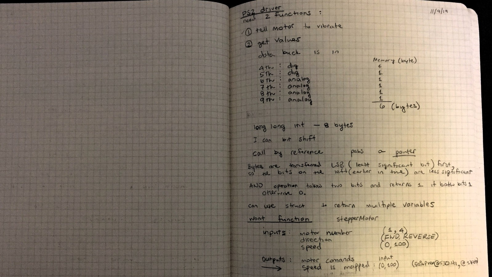
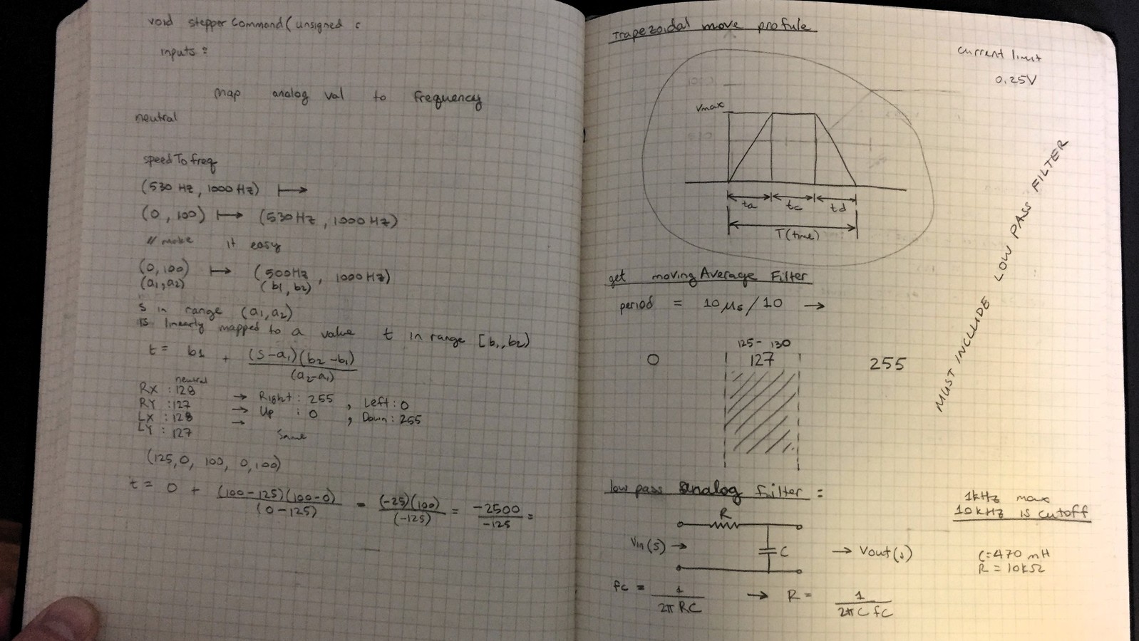
I’ve tried several methods to implement the square wave on the PIC32, including simple digital ON/OFF with a delay coupled with a low pass filter, but the most effective method was a Pulse Width Modulation (PWM) signal with a 50% duty cycle. The analog stick displacement provides 8-bit resolution to cover one-axis - in both positive and negative direction - an integer variable in the range 0-255, with the value of 127 corresponding to neutral position. With the use of my helped functions, I mapped the displacement value to the frequency of the PWM signal - not to be confused with the duty cycle. In other words, when the stick is barely pressed in any direction, the microcontroller produces a PWM signal at roughly 526 Hz, similarly, when the stick is pushed all the way to the max, the PWM signal is produced at 1 kHz.
My stepper motors are rated to produce 200 steps per revolution, that is 1.8 degrees per step. Let’s call it the baseline. So, if I run my motor at it’s baseline with a gear ratio of 1:4 (external to the motor), then I should expect the output shaft to spin at roughly 20 revolutions per minute (rpm), which is too fast for my application. To reduce the speed even further, there are two ways: (1) mechanical: gear train and/or (2) software/electrical: make the angular displacement for each step smaller - microstepping. From the data sheet, there are 3 pins on the driver that control the resolution of the step, based on the digital signal you supply. For now, I left these pins floating, expecting to return to them at a further development stage.
Driver for Playstation 2 Wireless Controller
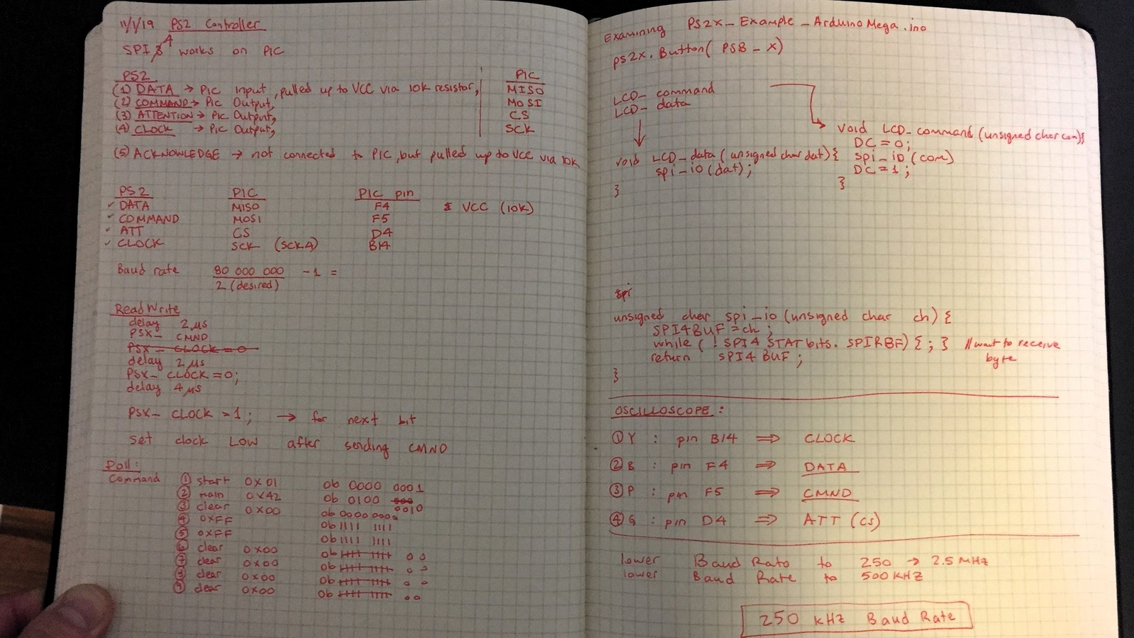
Communication
Serial Peripheral Interface (SPI)-like: 9 8-bit transactions per communication instance at 250 kHz Baud Rate (determined this rate myself through experimentation), but with bits reversed (i.e. the least significant bit is the most significant bit, and vise versa). All available documentation relied on bit bagging, while I relied on the SPI peripheral that came with PIC32. Talk about debugging!
More coming soon…
Control
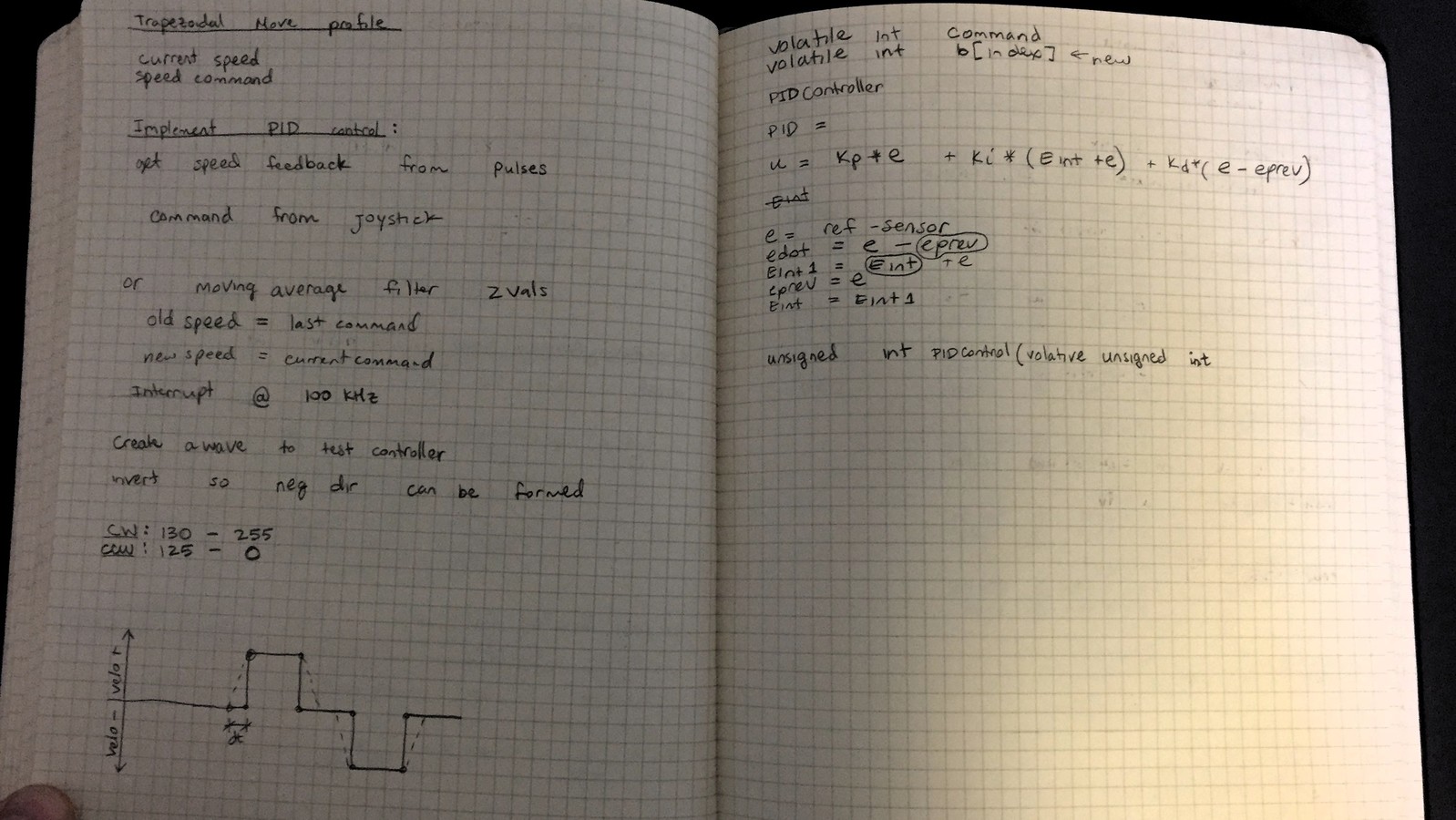
Trapezoidal velocity profile using moving average filter and a deadband centered around the neutral value.
Details coming soon…
Pictures
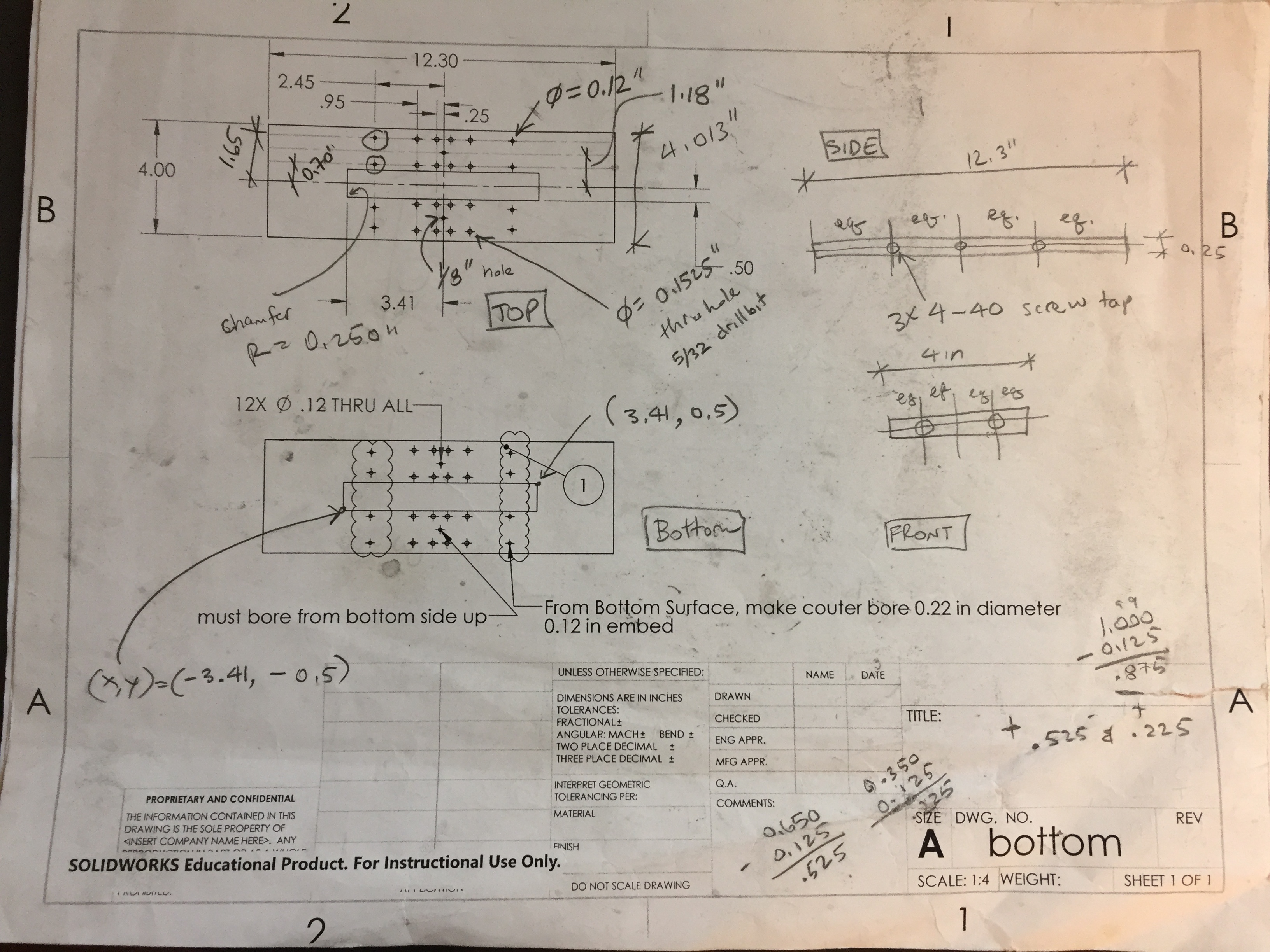
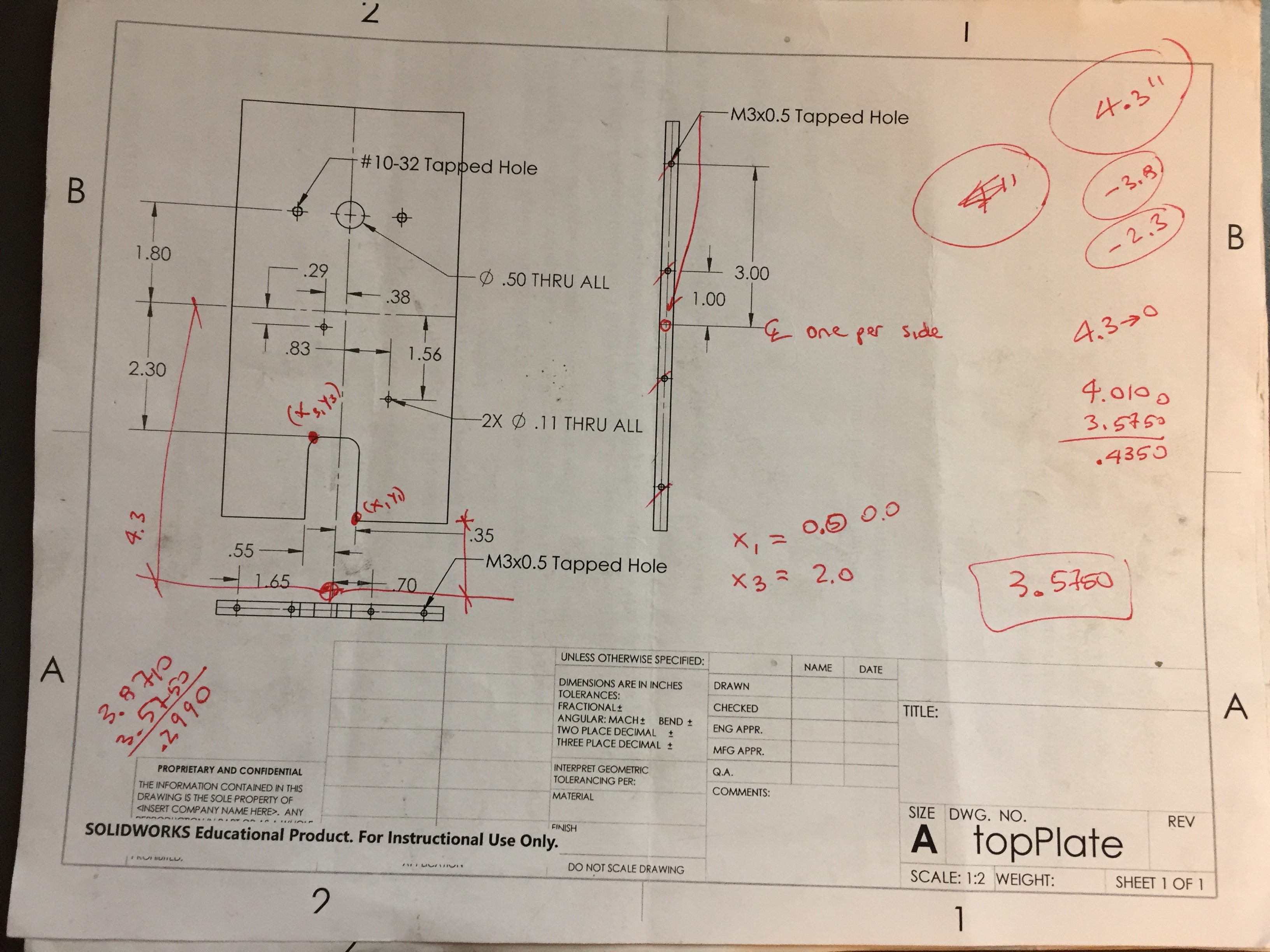
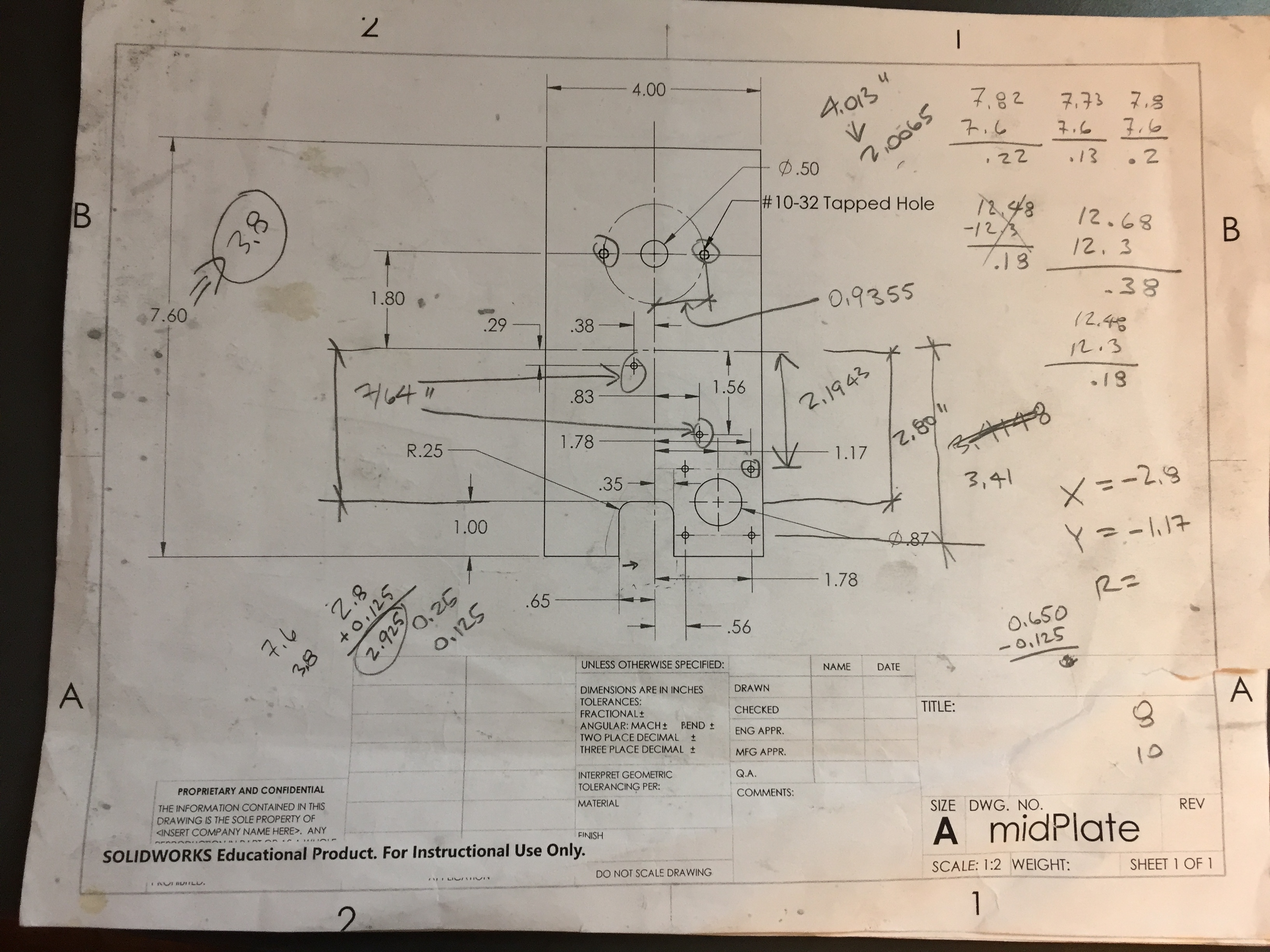
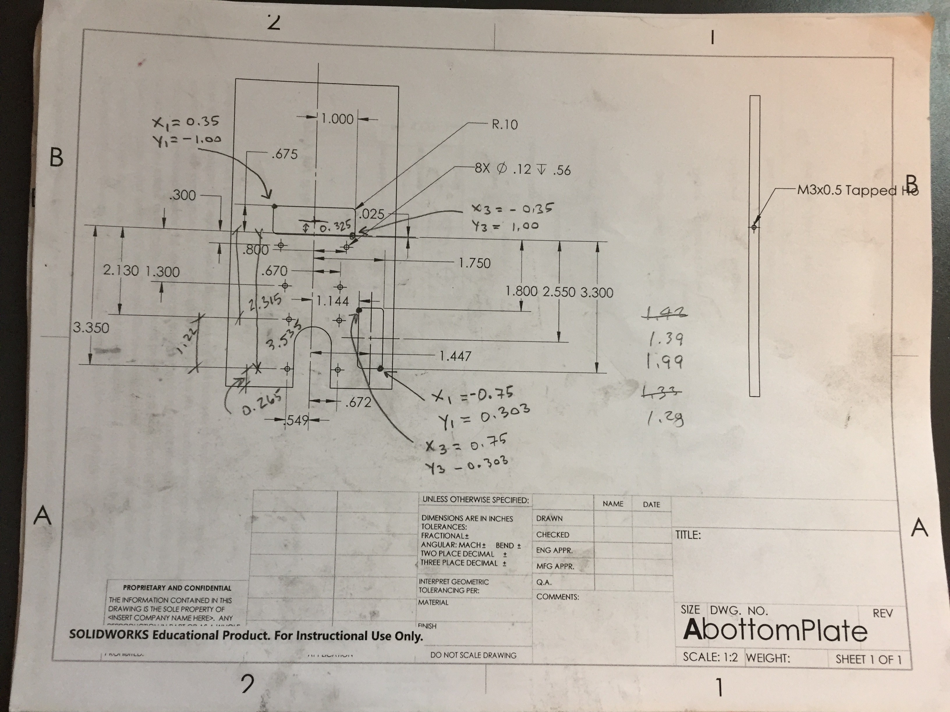
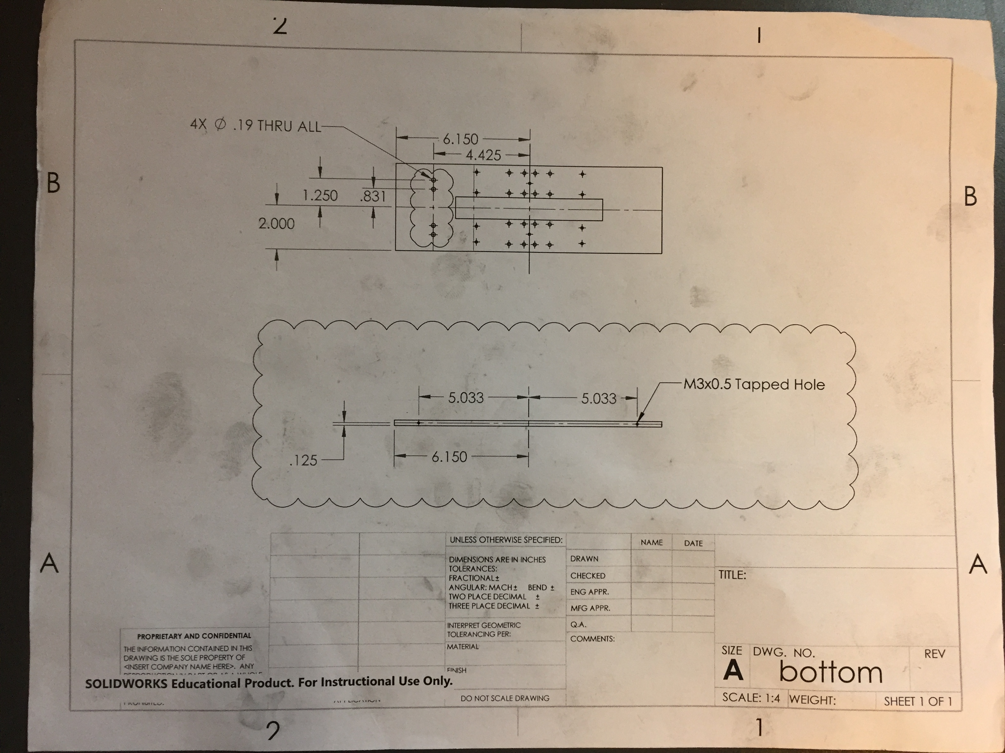
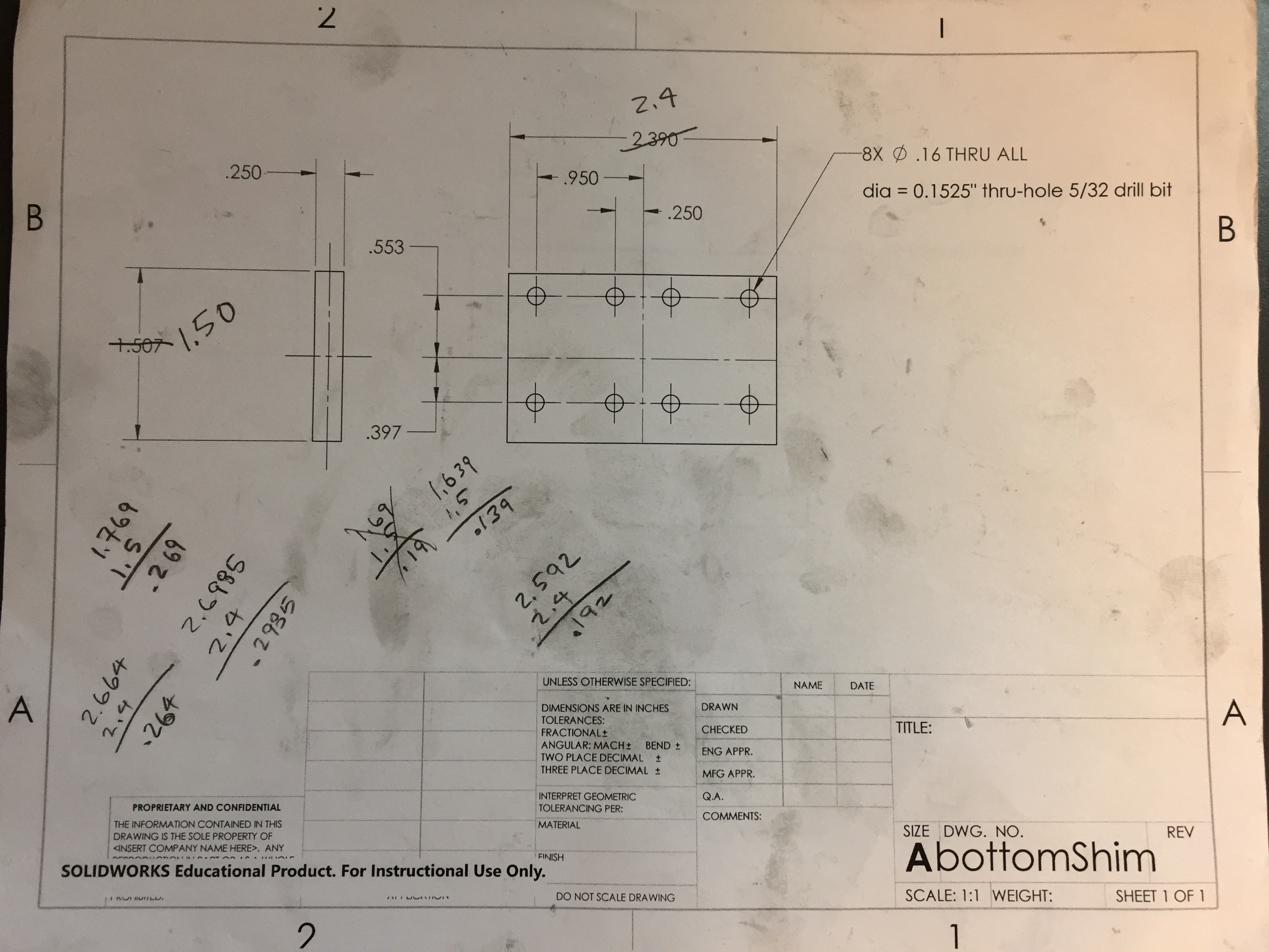
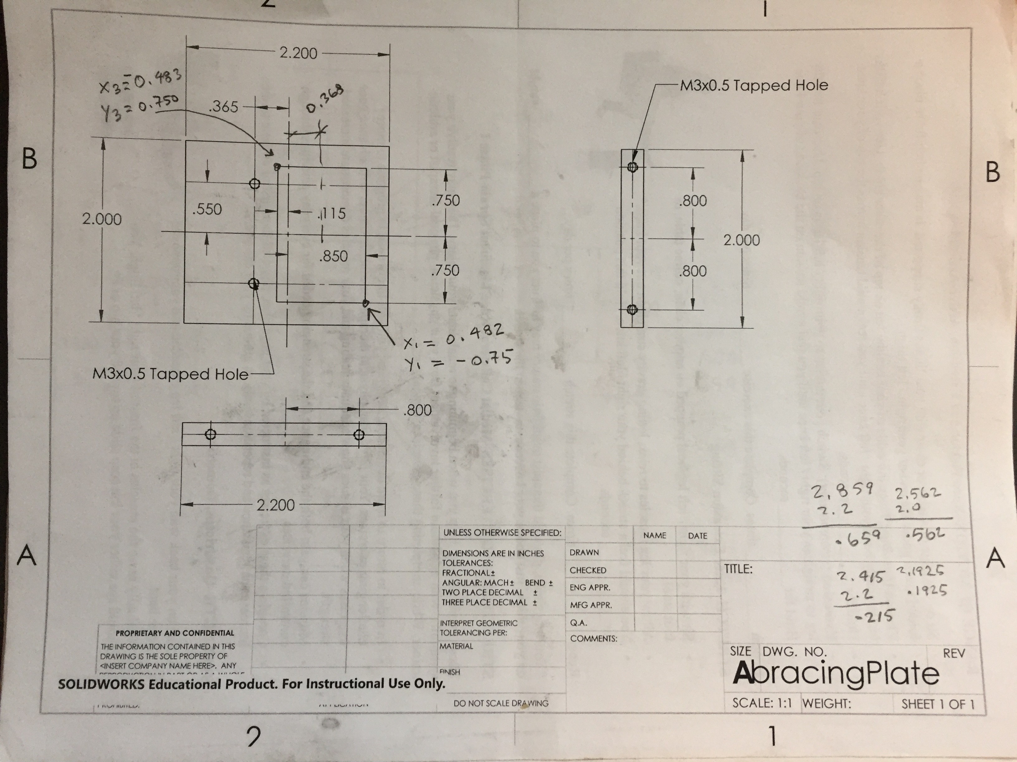
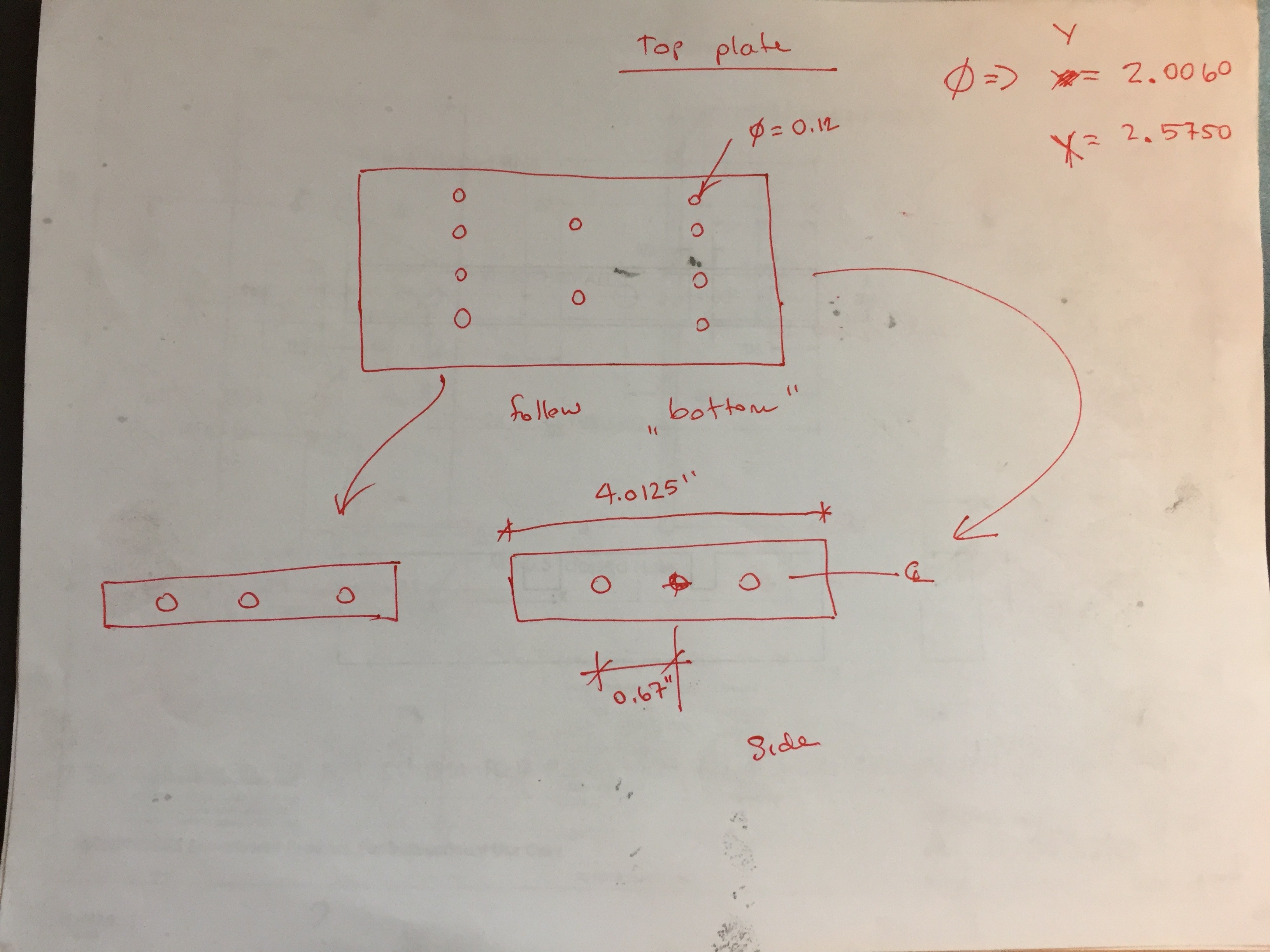
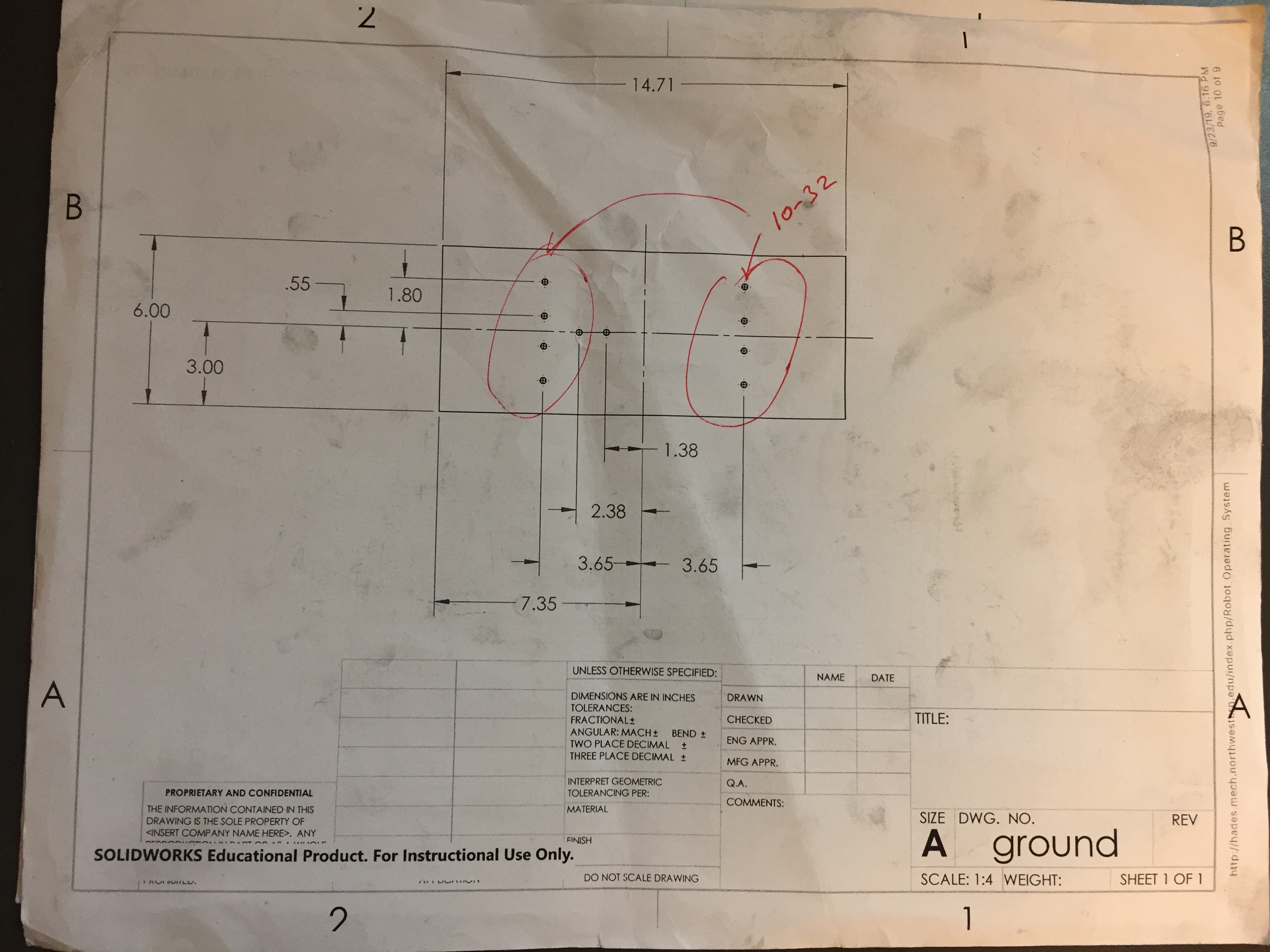
Design Notebook

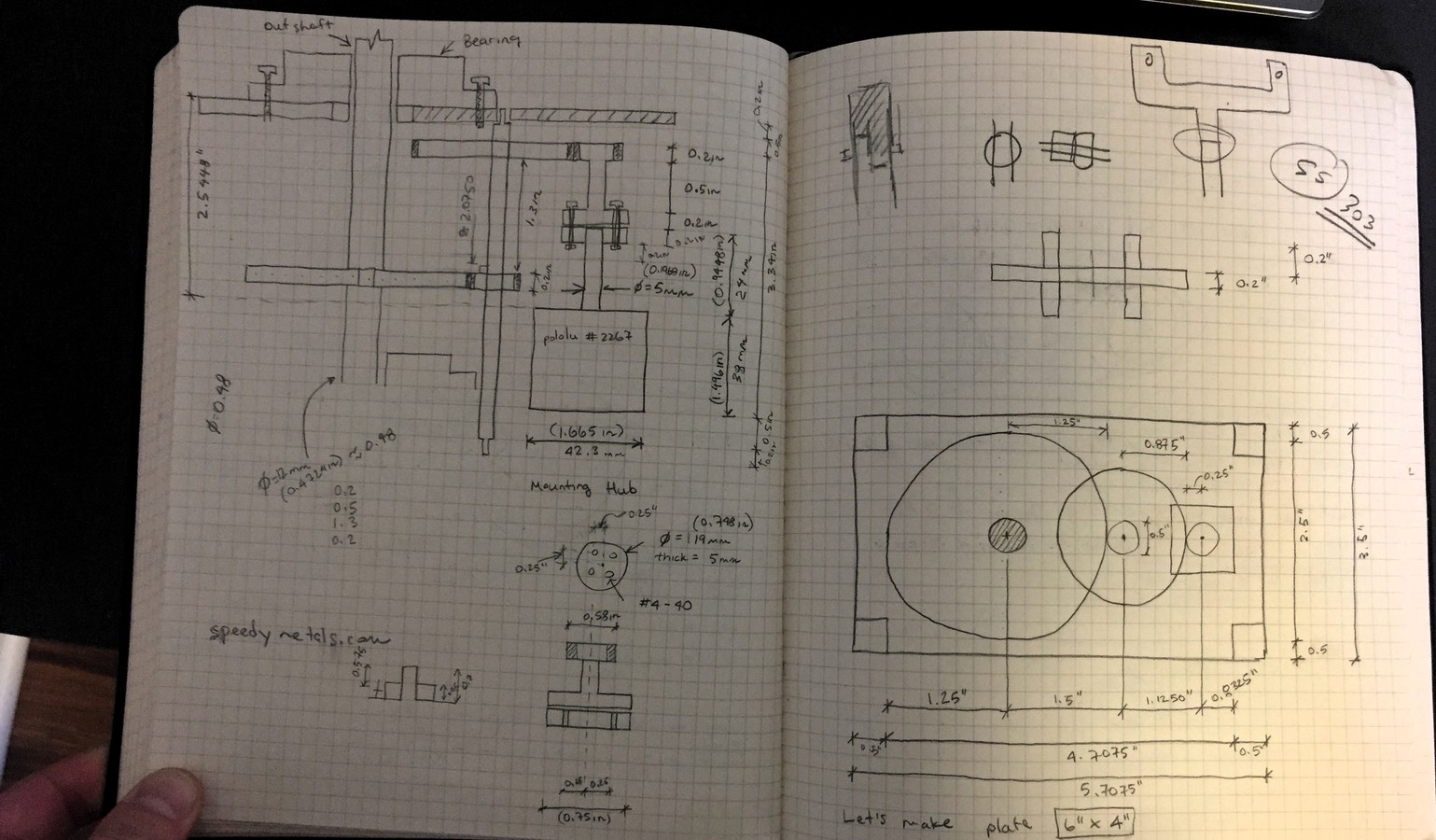
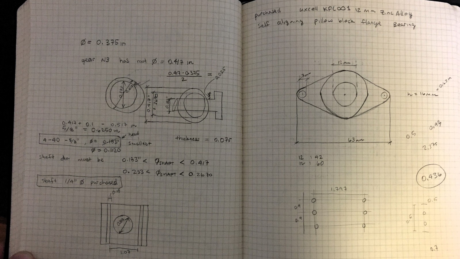
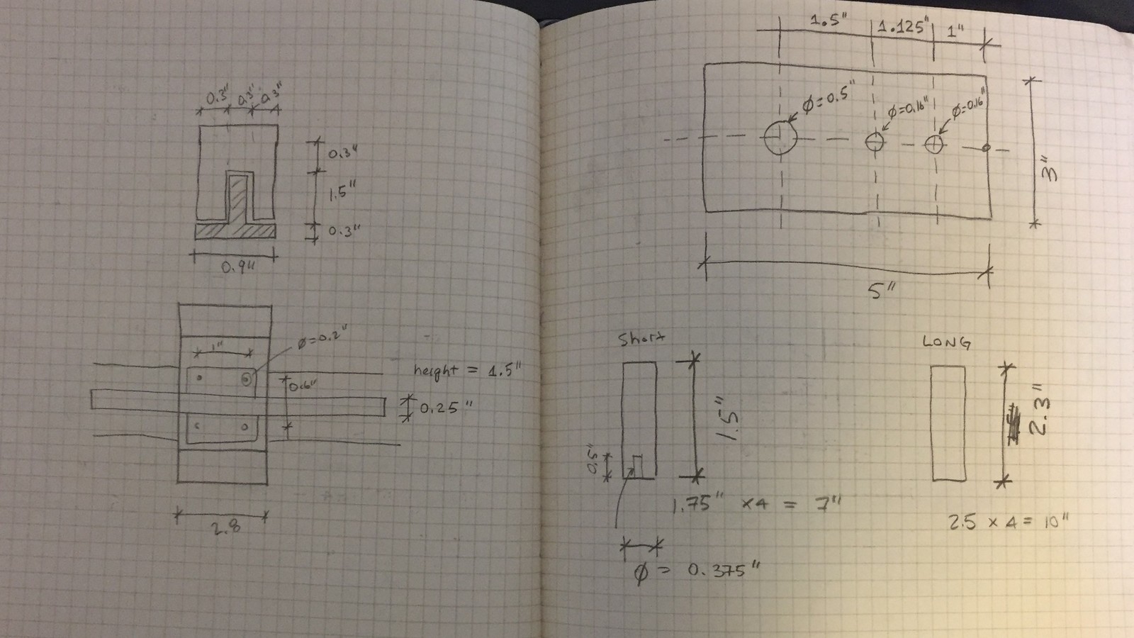
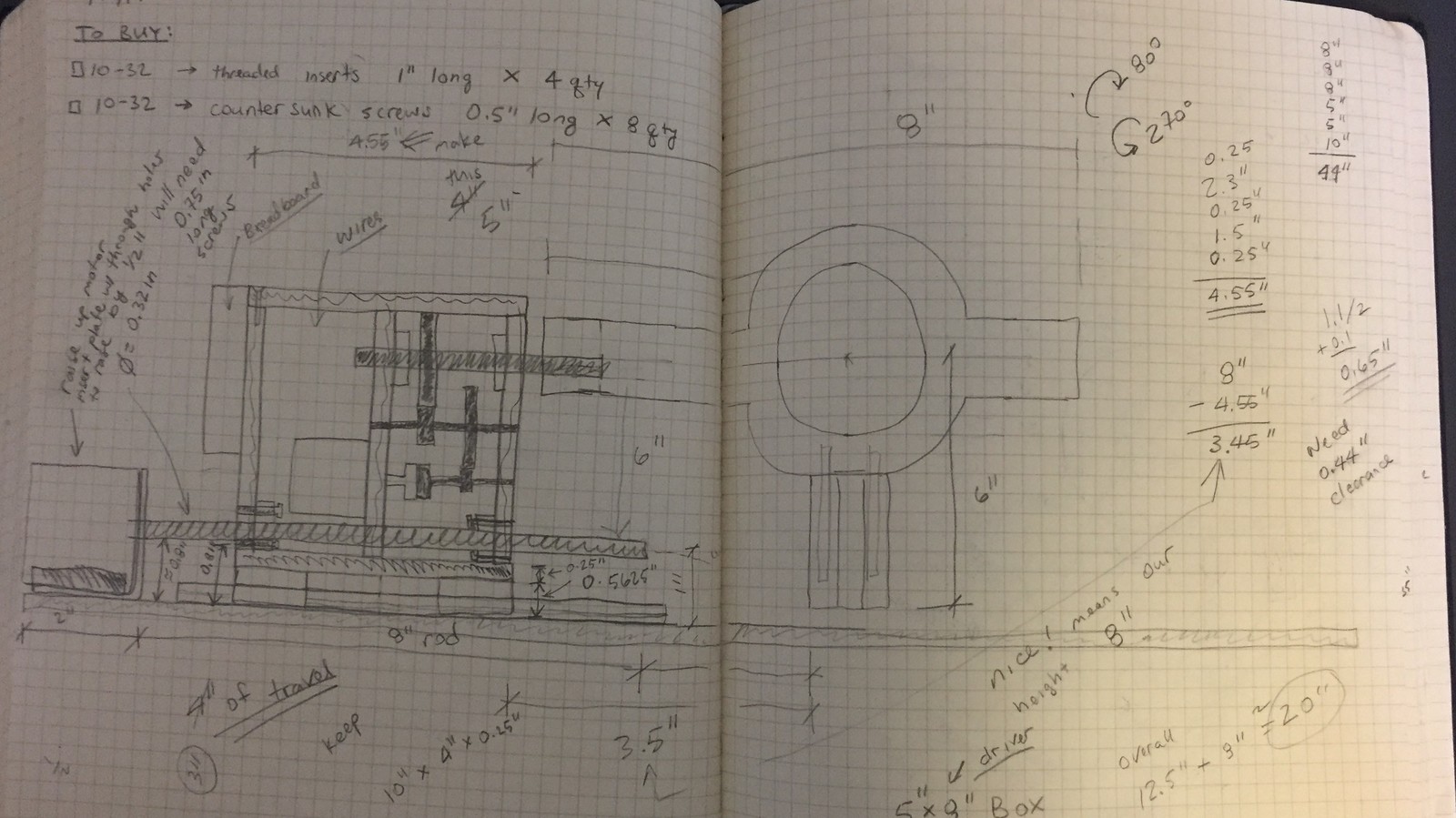
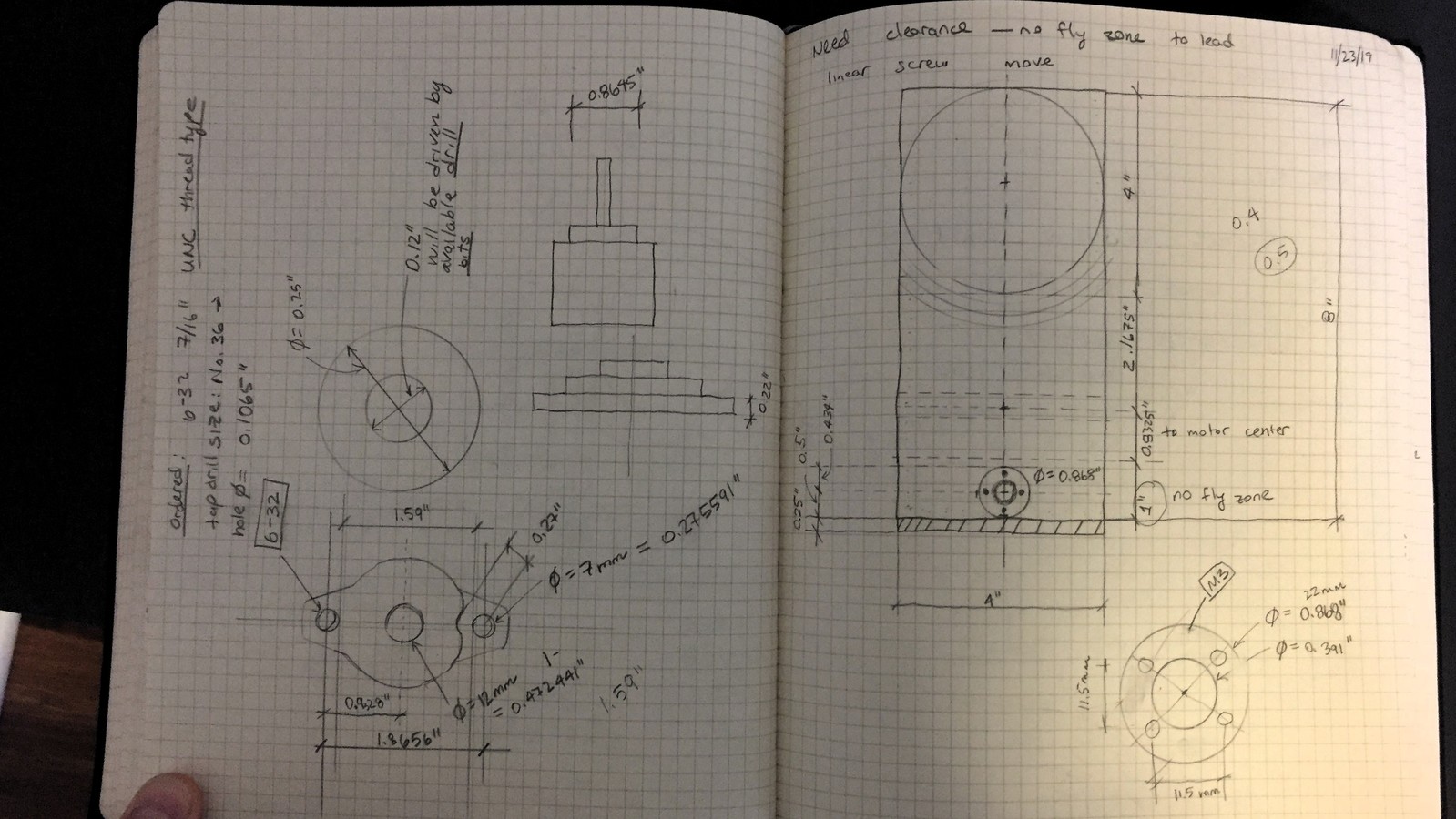
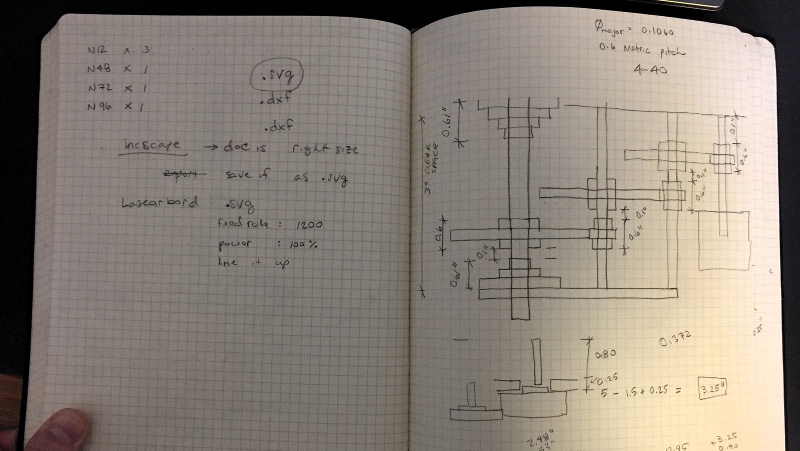
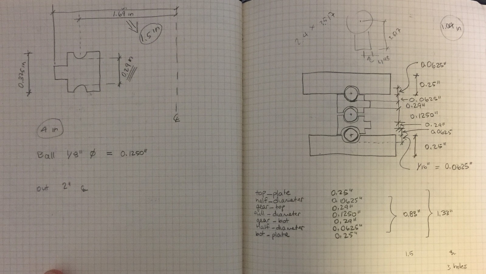
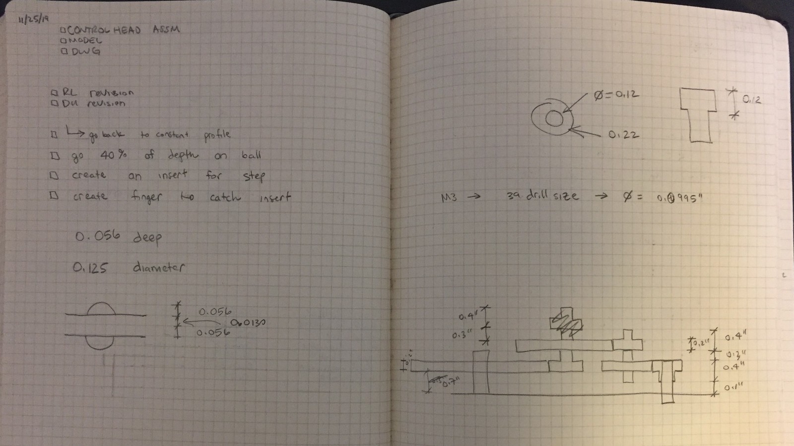
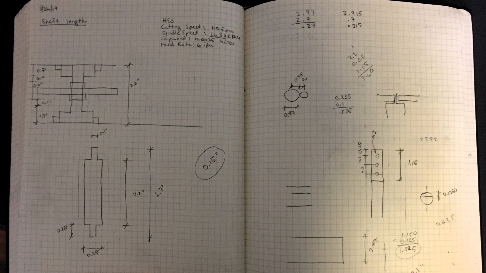
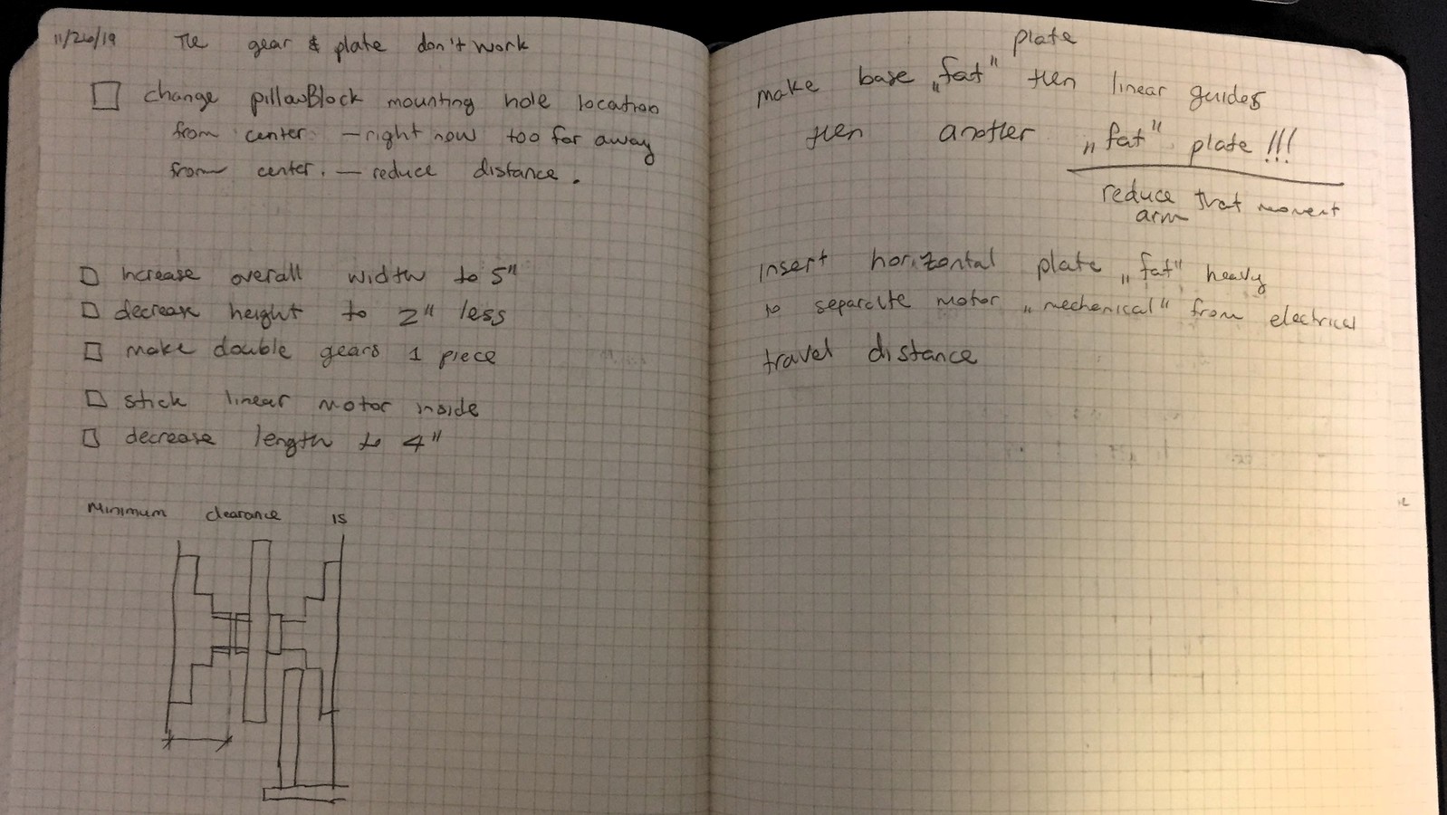
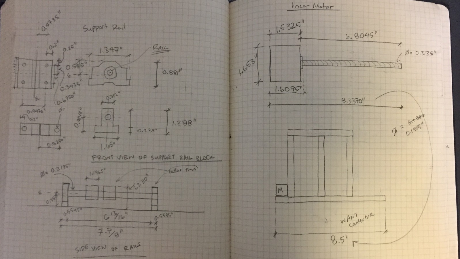
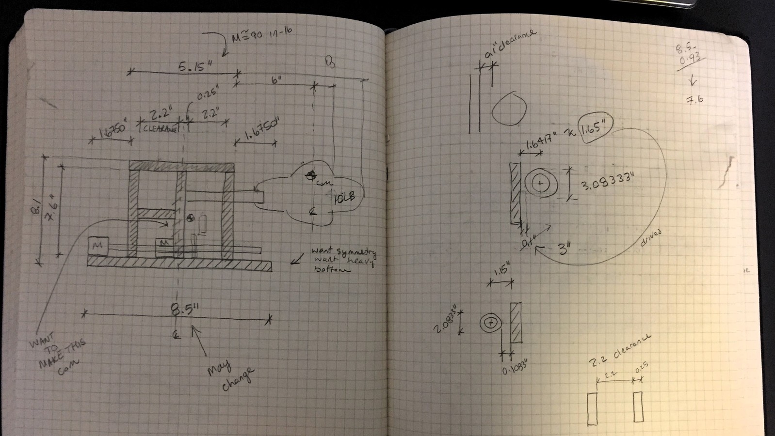
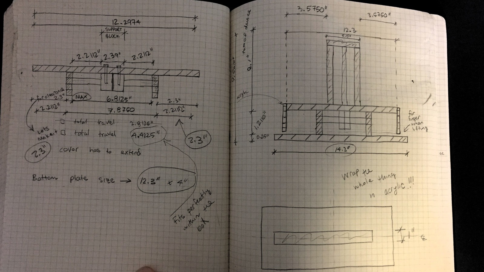
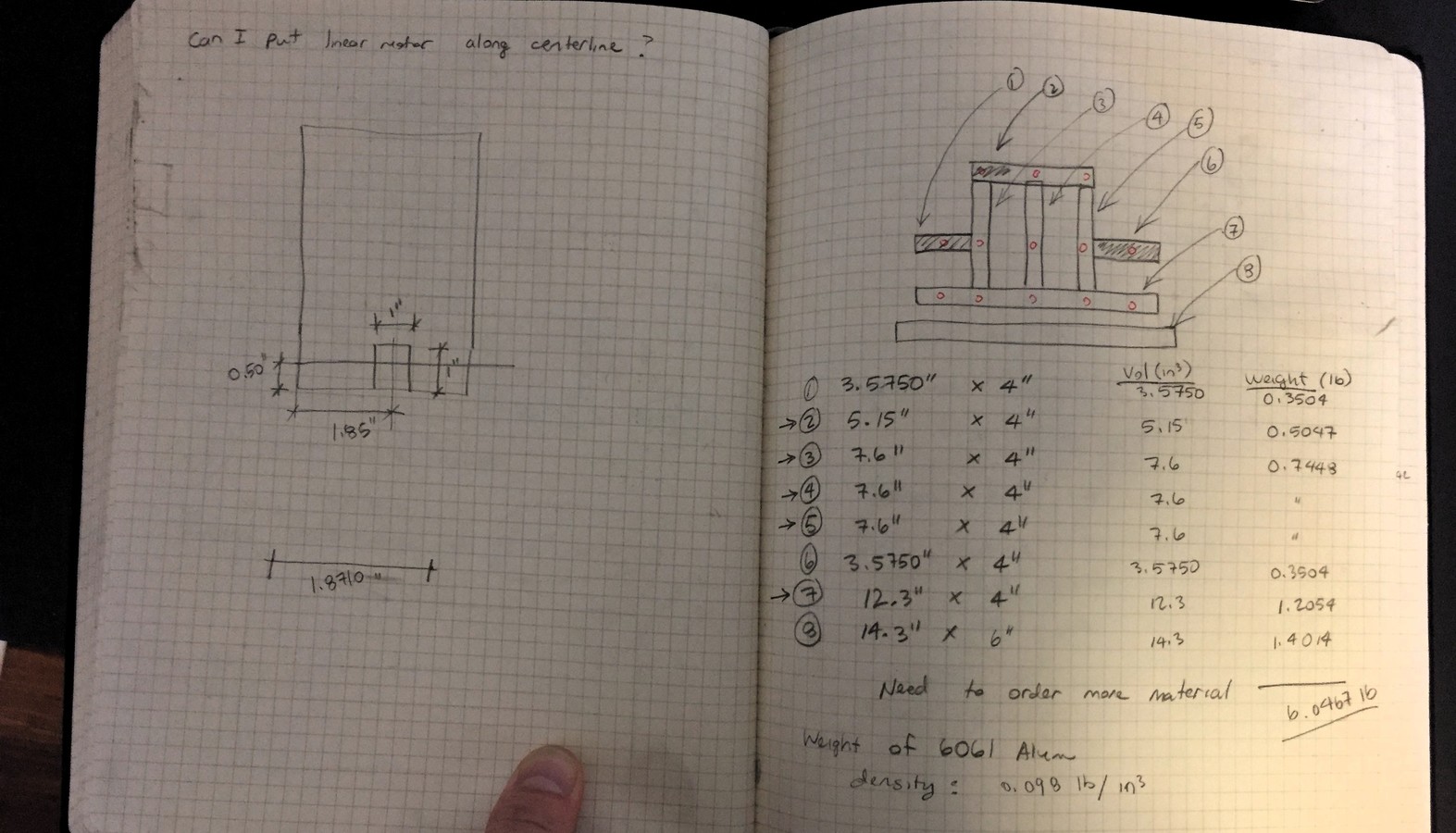
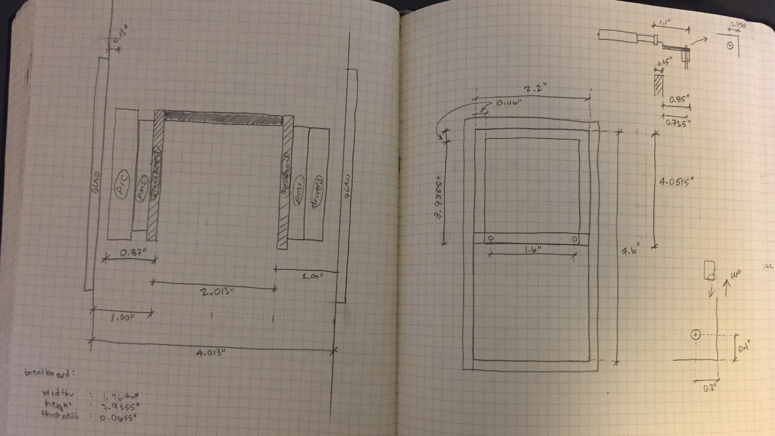
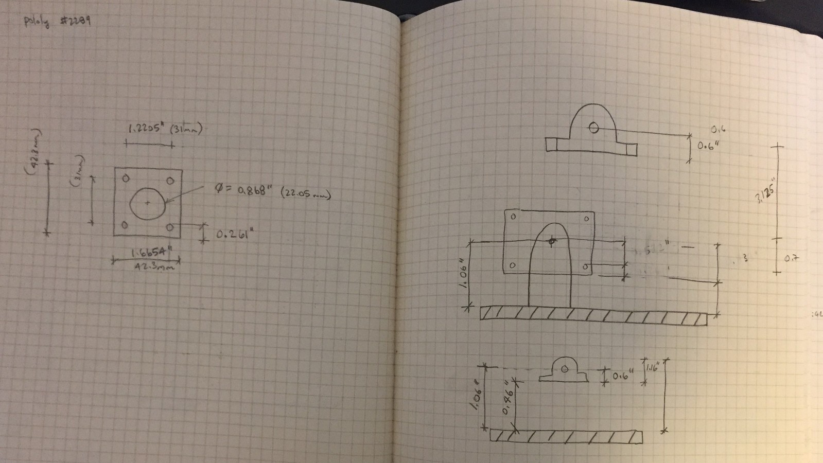
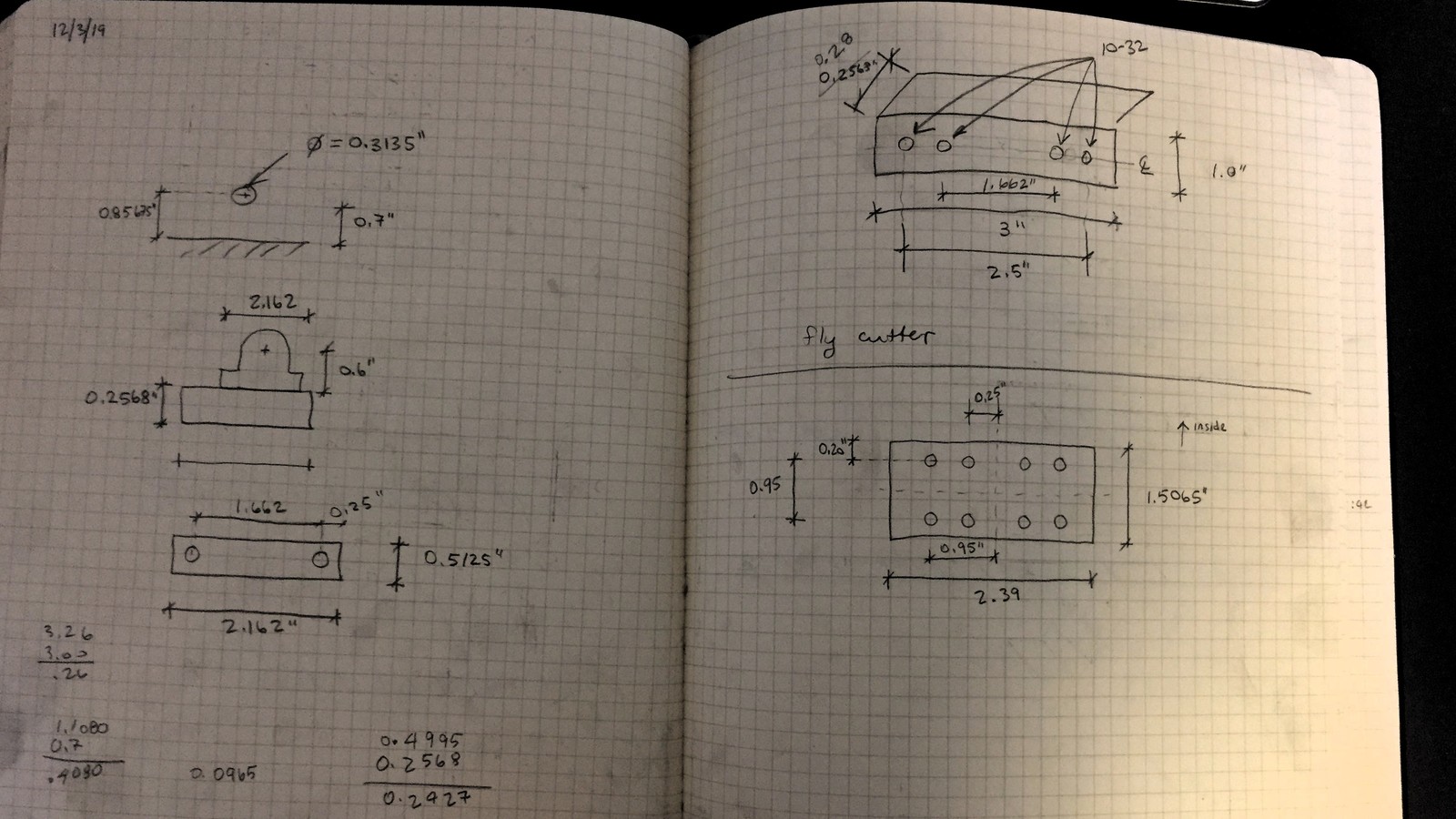
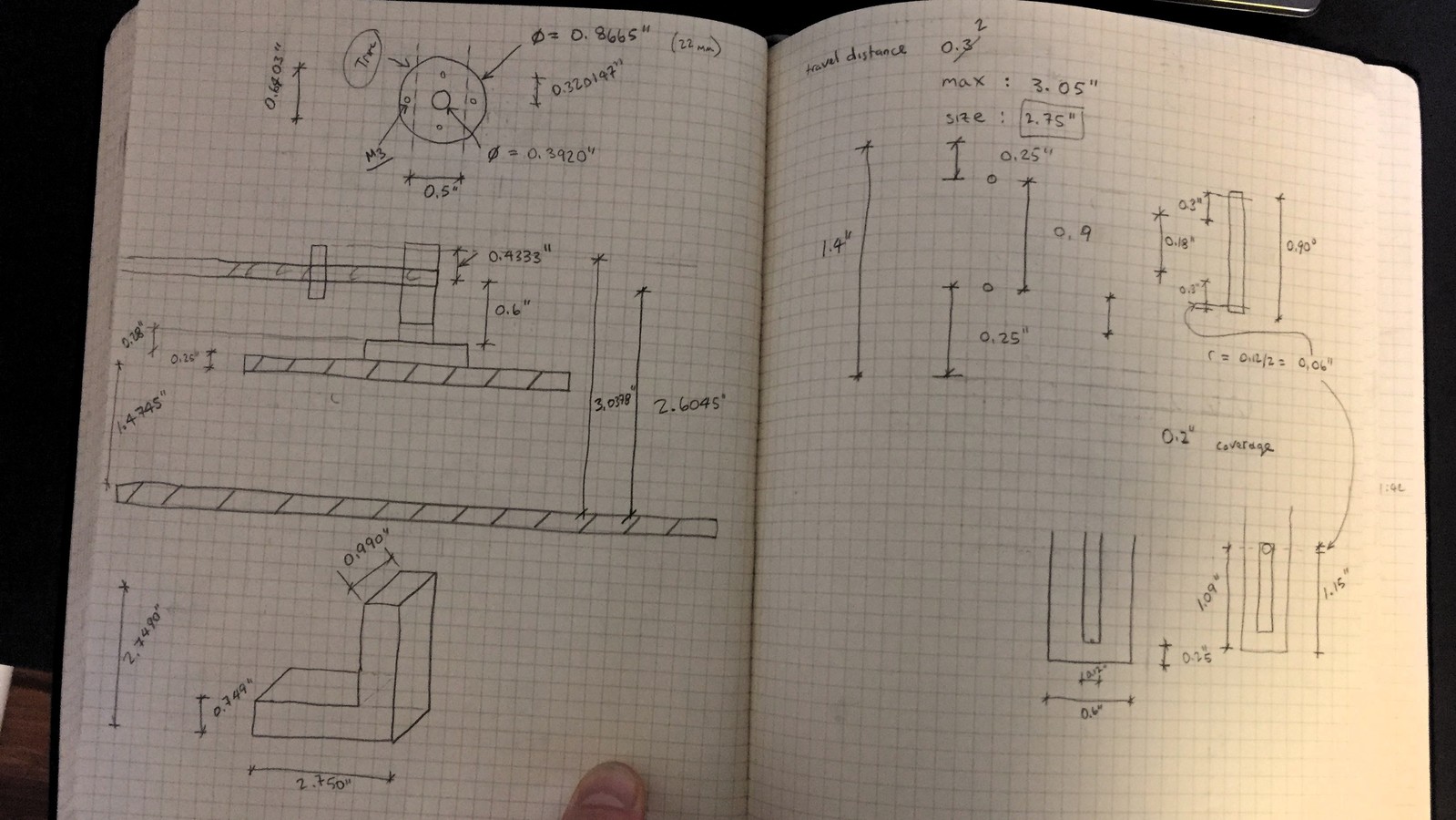
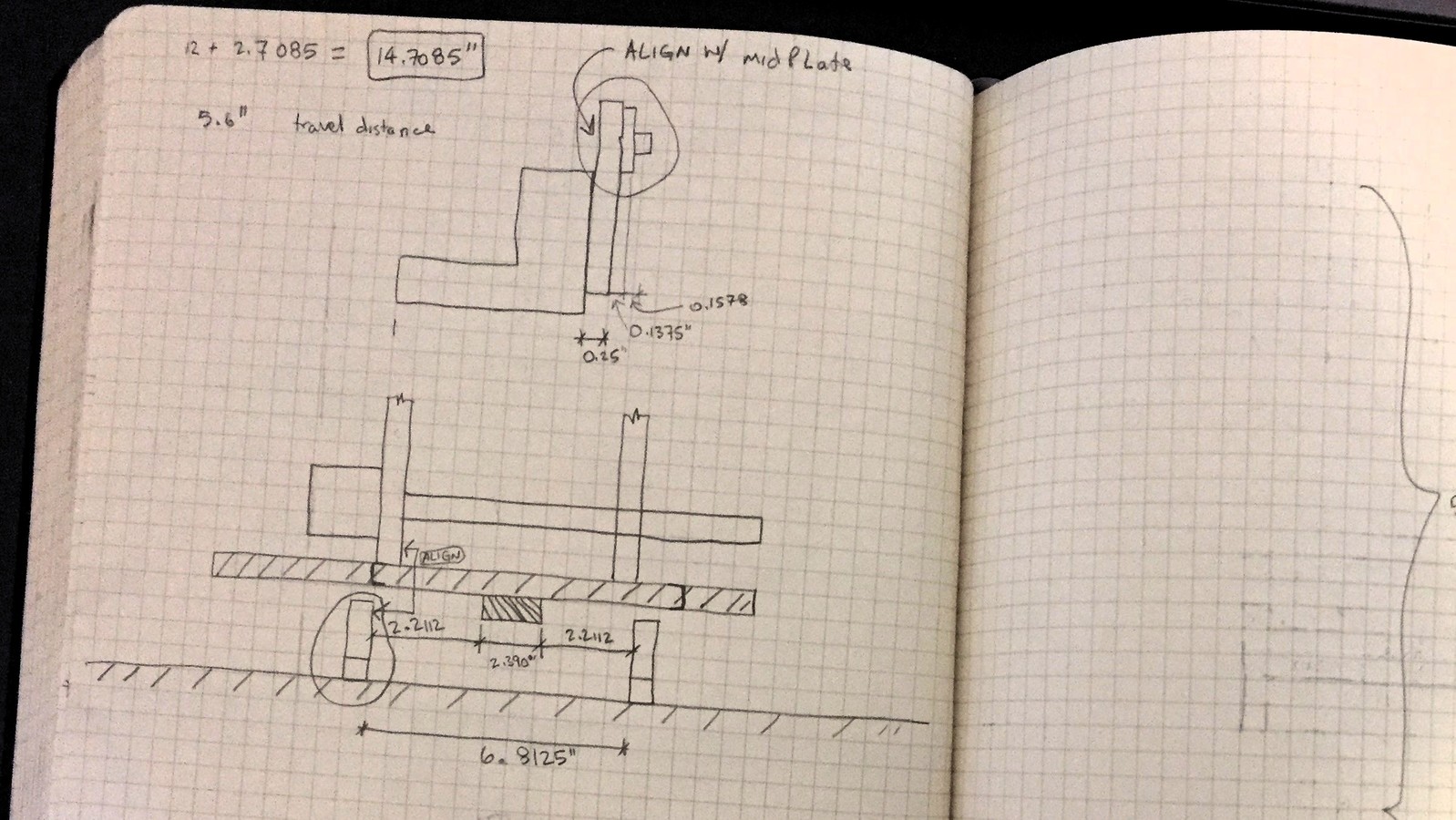
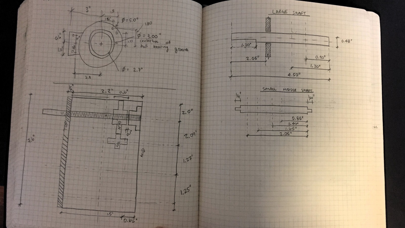
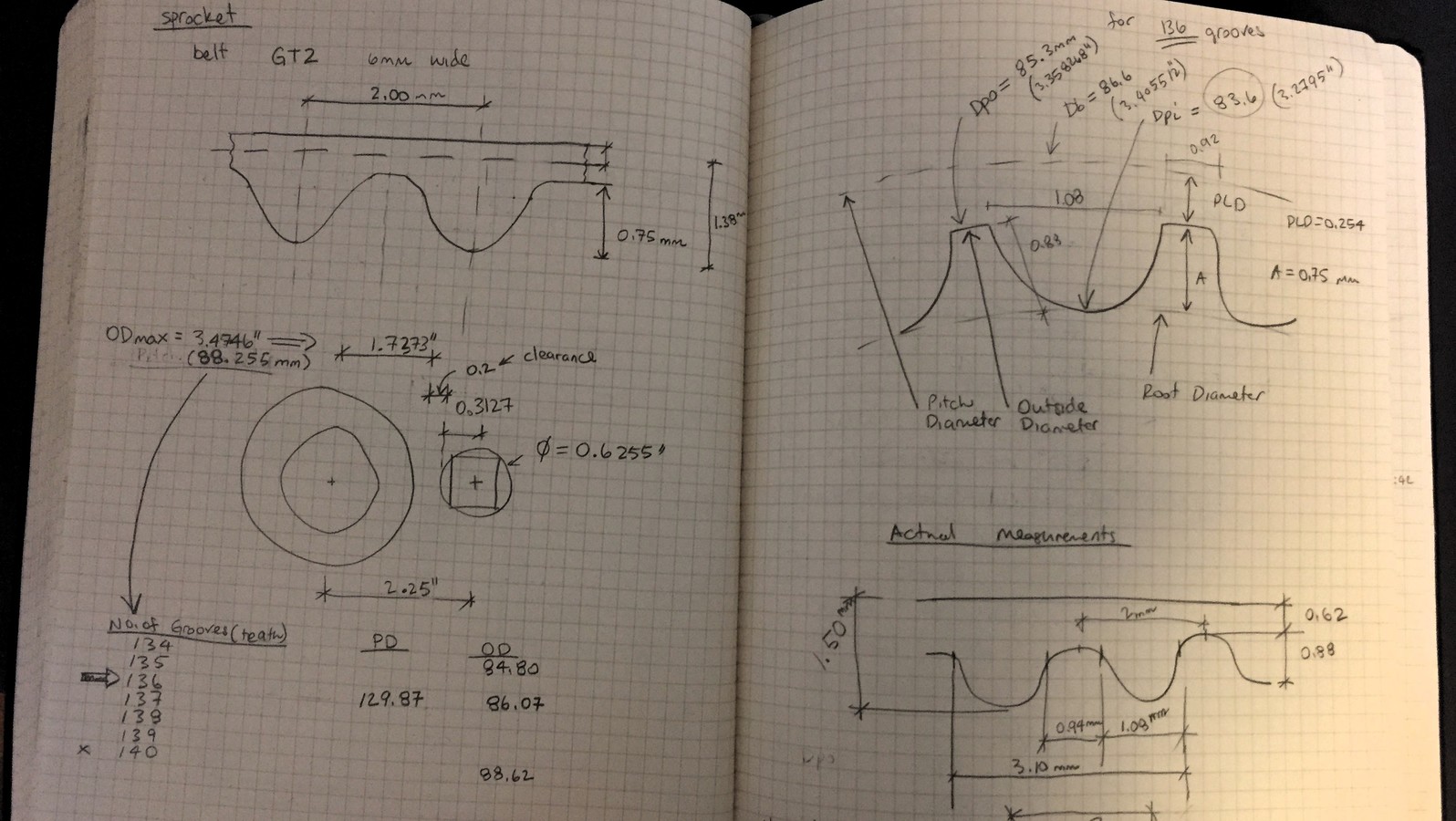
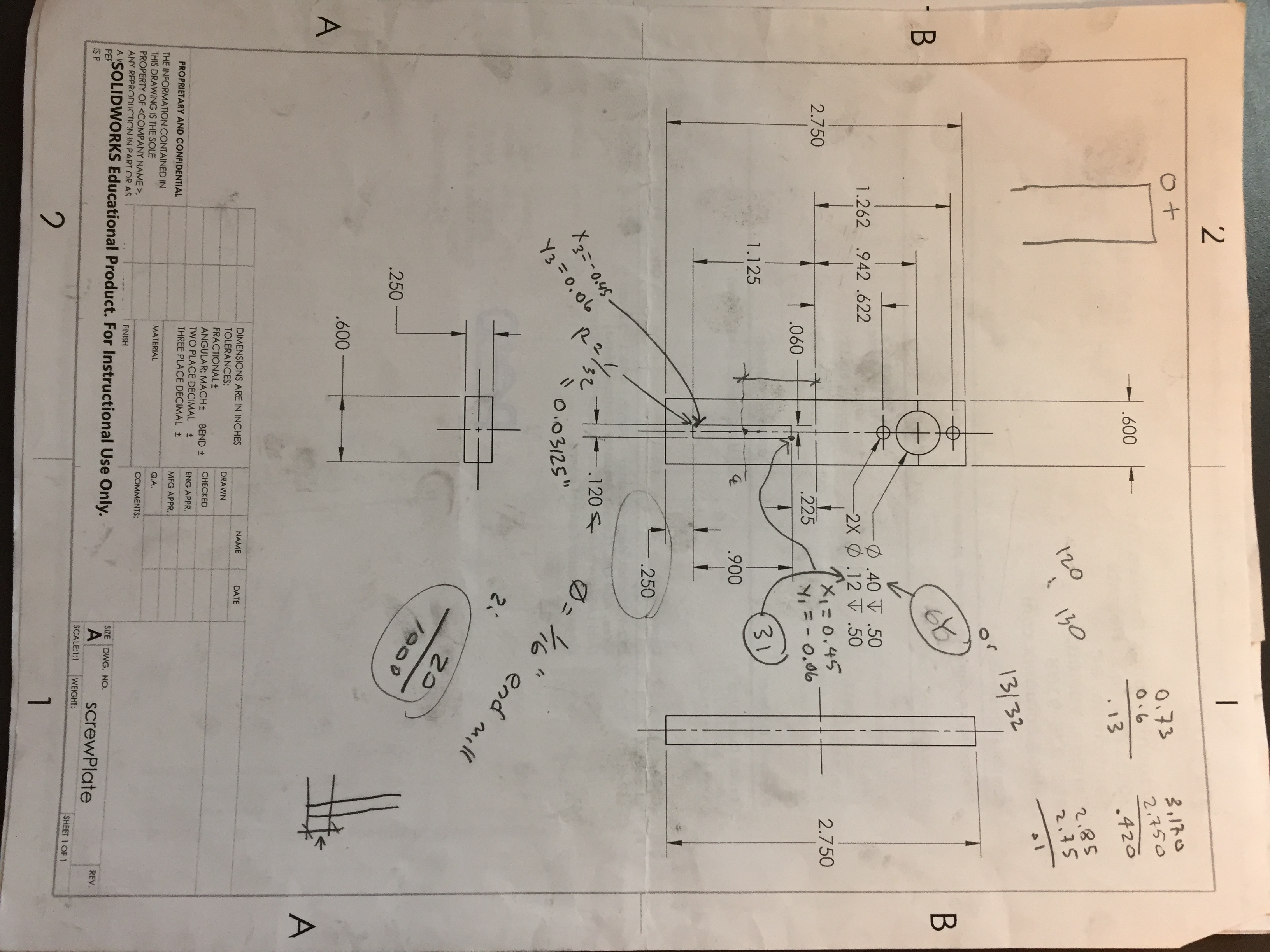
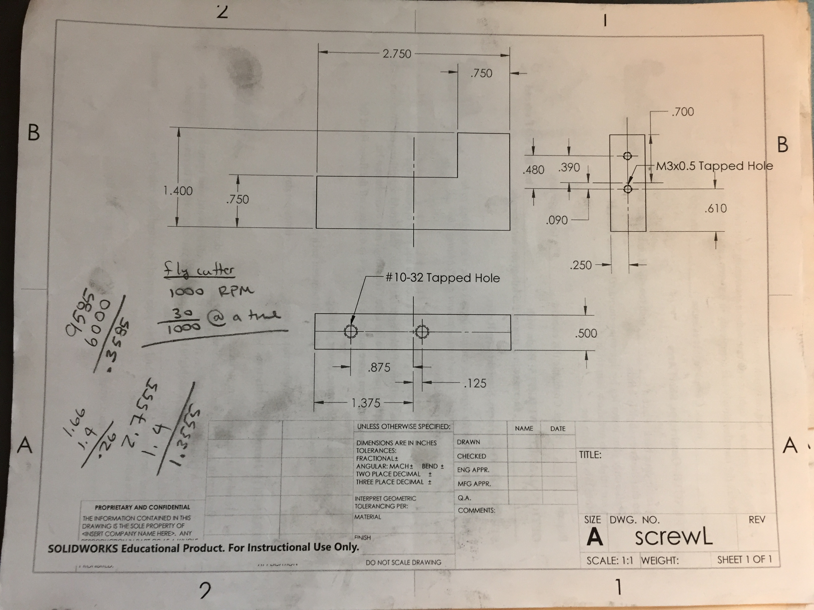
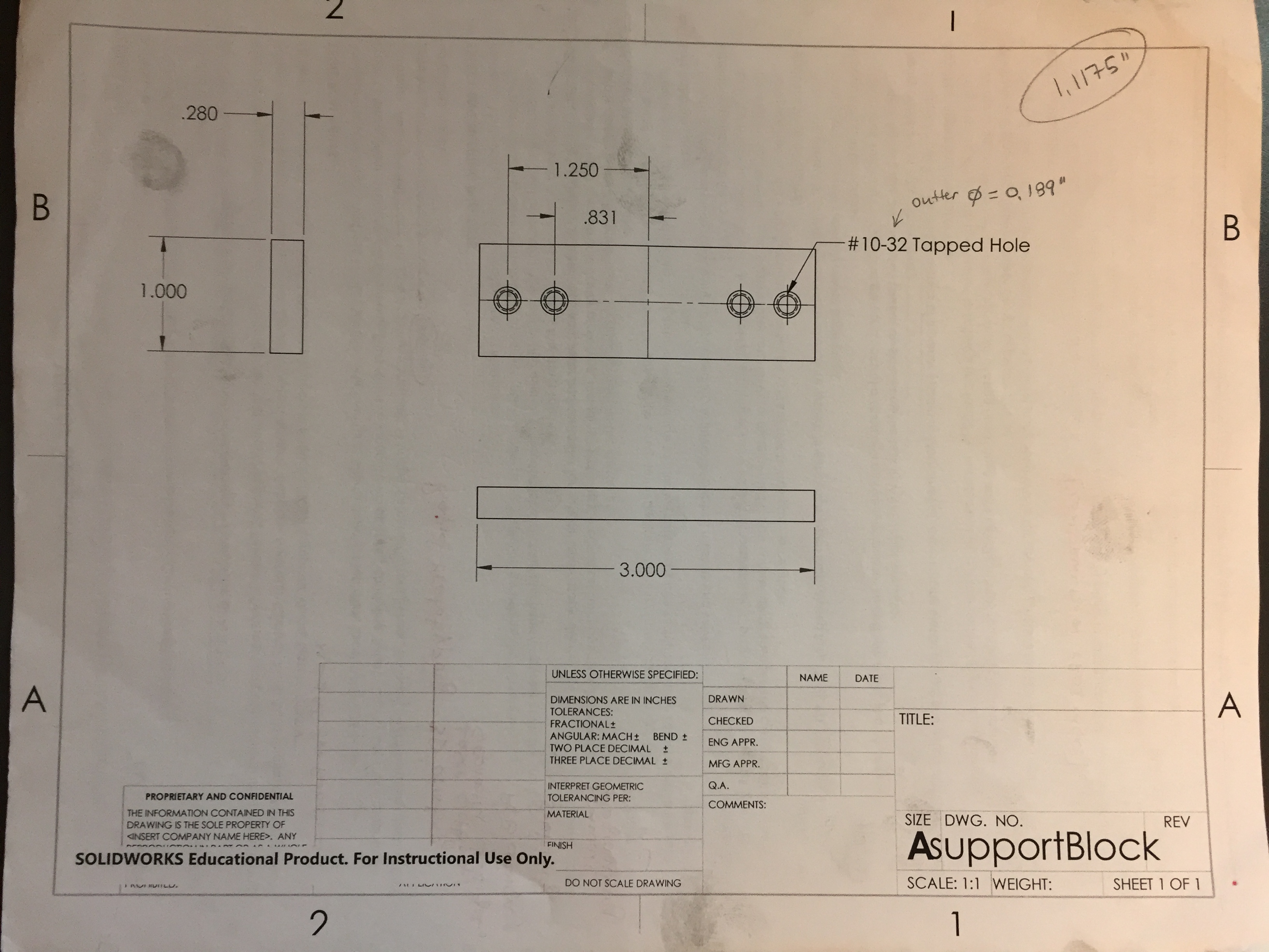
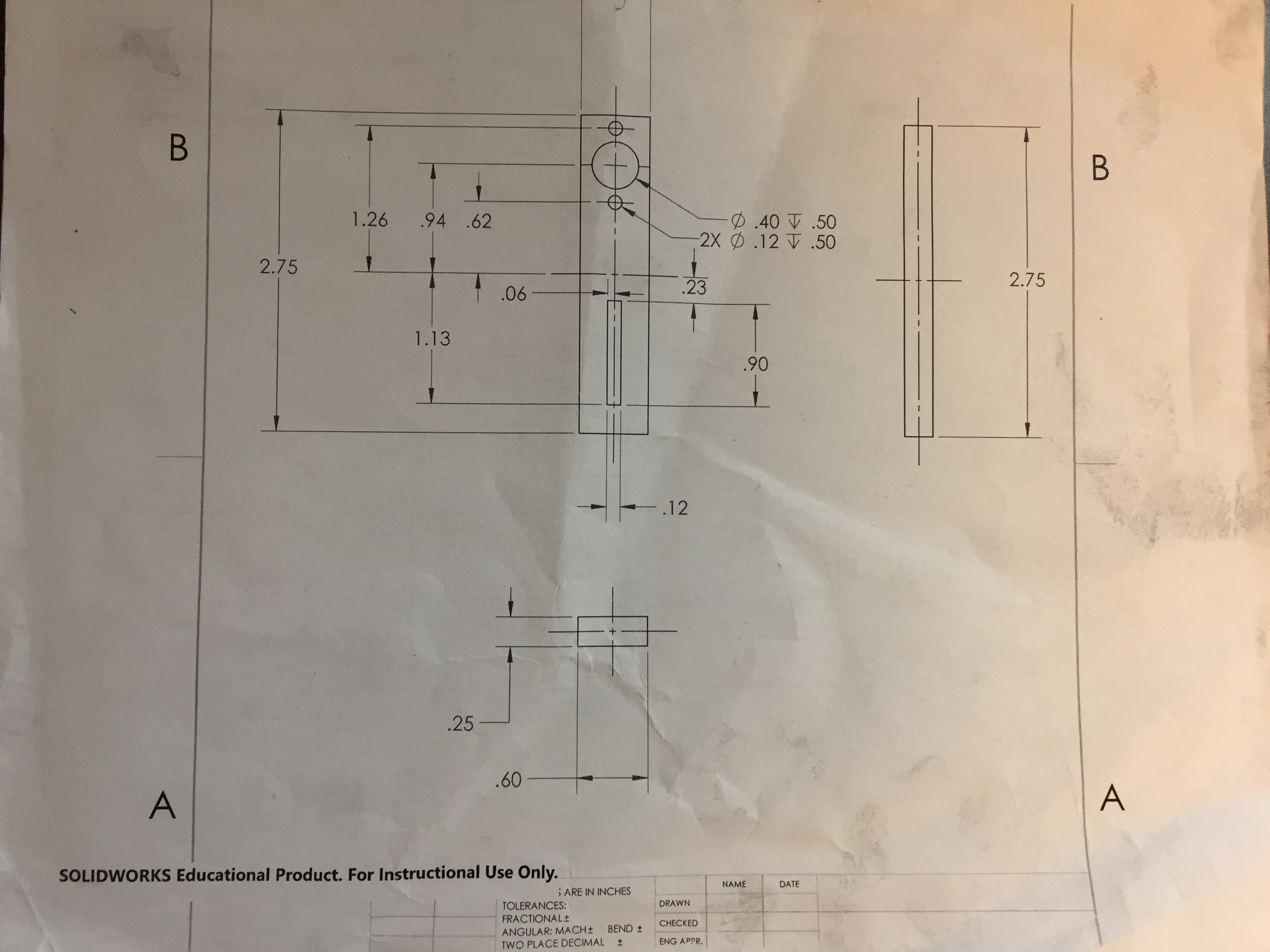
Plans for Machining
Note the grease on the sheets!
More Videos
- dialRotator Concept
- Demo: stepper motor control - replaced
- dialRotator_concept2
- linearActuator Control
- PS2 Control
- Control of all motors
- Demo of version 1 functionality
- CNC 2-axis Bottom Plate Pocket
- Version 2 Linear Actuation
- CNC Routine for Instrument topPlate